空气滤清器外壳模具设计(含CAD零件图和装配图)
来源:56doc.com 资料编号:5D11256 资料等级:★★★★★ %E8%B5%84%E6%96%99%E7%BC%96%E5%8F%B7%EF%BC%9A5D11256
资料以网页介绍的为准,下载后不会有水印.资料仅供学习参考之用. 密 保 惠 帮助
资料介绍
空气滤清器外壳模具设计(含CAD零件图和装配图)(选题审批表,任务书,开题报告,中期检查表,论文说明书19400字,CAD图13张,工序卡11张,工序图11张,答辩PPT)
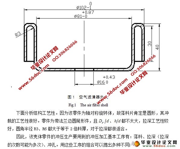
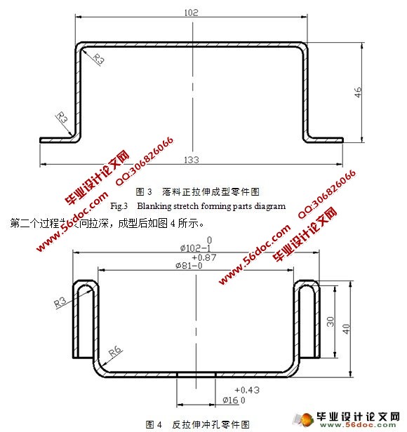
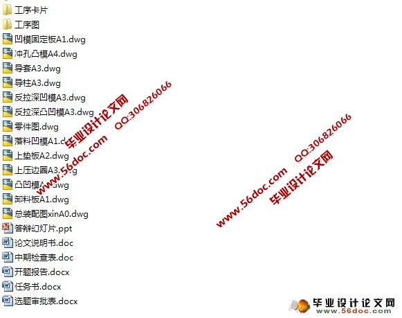
摘 要:该零件来源于生产实际。通过对零件的工艺分析,提出了落料正反拉伸冲孔复合模成形工艺。其次我还对对模具的排样做了精确分析,很好的提高了材料利用率和生产效率。本复合模采用正装形式,通过对毛坯和零件外形尺寸的计算,我得出模具各部分刃口尺寸,并以此设计计算出各主要零部件外形尺寸。其次还列出了模具所需零件的详细清单,并对模具闭合高度进行了合理的确定,设计出了装配图。通过对各工艺力的计算初步选定了压力机并进行了闭合高度校核和功率校核。最后对模具的一个主要零部件反拉伸凸凹模进行了简单的加工工艺路线制定,并制作了工序卡片。
关键字:复合模;空气滤清器外壳;冲压工艺。
The Design of the Air Filter Shell Mould
Abstract: The parts come from the practice production. Through the analysis of the technology of spare parts, the blanking tensile punching composite die and forming process was put forward. Further I make an exact analysis to the blank layouts; which improve the material utilization and production efficiency. This composite mould adopt a formal assembling form, through the blank and parts size calculation, I get the mold size of cutting edge. And through it the boundary dimension of the main parts was design out. Further I make a detail list of the needed components, and fix the die shut height reasonably; draft the assembly drawing .The press machine is selected through the technology force calculation, and the shut height as well as power is checked. Finally one of the major components of the mould-the anti-drawing die have been simply formulated the routing,and produced the process card.
Key words:Composite die; The air filter shell; Stamping process.
目 录
摘要…………………………………………………………………………………………1
关键词………………………………………………………………………………………1
1 前言……………………………………………………………………………………2
1.1 零件材料的分析…………………………………………………………………2
1.2 冲压技术的发展…………………………………………………………………3
2 冲压工艺分析……………………………………………………………………………4
2.1 零件材料的分析…………………………………………………………………4
2.2 零件工艺性能分析………………………………………………………………5
3 确定工艺方案……………………………………………………………………………6
3.1 计算毛坯尺寸……………………………………………………………………6
3.2 计算拉伸次数……………………………………………………………………9
3.2.1 正拉伸……………………………………………………………………9
3.2.2 反拉伸……………………………………………………………………9
3.3 确定工艺方案与模具形式……………………………………………………10
4 主要工艺参数计算……………………………………………………………………11
4.1 确定排样冲裁方案……………………………………………………………11
4.2 确定各中间工序尺寸…………………………………………………………12
4.3 计算工艺力、初选设备…………………………………………………………14
4.3.1 落料、正拉伸过程………………………………………………………14
4.3.2 反拉伸、冲孔过程顶件力………………………………………………15
4.3.3 拉伸功的计算…………………………………………………………16
4.3.4 初选压力机……………………………………………………………16
5 模具的结构设计………………………………………………………………………17
5.1 模具结构形式的选择…………………………………………………………17
5.2 模具工作部分尺寸的计算……………………………………………………18
5.2.1 落料……………………………………………………………………18
5.2.2 正拉伸…………………………………………………………………20
5.2.3 反拉伸…………………………………………………………………20
5.2.4 冲孔……………………………………………………………………20
6 主要零部件的设计及计算……………………………………………………………21
6.1 落料凹模………………………………………………………………………21
6.2 凸凹模…………………………………………………………………………22
6.3 反拉伸凸凹模(拉伸凸模和冲孔凹模)……………………………………23
6.3.1 凸模的结构设计………………………………………………………23
6.3.2 拉伸凸模结构…………………………………………………………24
6.4 反拉伸凹模……………………………………………………………………25
6.5 冲孔凸模………………………………………………………………………26
6.6 弹性卸料板……………………………………………………………………27
6.7 上垫板…………………………………………………………………………29
6.8 凹模固定板……………………………………………………………………30
7 选定冲压设备…………………………………………………………………………30
7.1 压力机的规格…………………………………………………………………30
7.2 电动机功率的校核……………………………………………………………31
8 选用模架,确定闭合高度……………………………………………………………32
8.1 模架的选用……………………………………………………………………32
8.2 模具的闭合高度………………………………………………………………32
8.3 压力中心………………………………………………………………………33
9 模具的装配……………………………………………………………………………33
9.1 复合模的装配…………………………………………………………………33
9.2 凸、凹模间隙的调整…………………………………………………………33
10 模具的整体安装………………………………………………………………………34
10.1 模具的总装配…………………………………………………………………34
10.2 模具零件………………………………………………………………………34
11 主要零件的工艺加工过程…………………………………………………………36
12 结论……………………………………………………………………………37
参考文献……………………………………………………………………………………38
致谢……………………………………………………………………………………… 38
附录
附录1:机械加工工序卡片
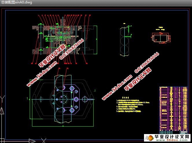
附录2:模具总装配图 1张A0图纸
附录3:主要零部件图 3张A1图纸,2张A2图纸,5张A3图纸,1张A4图纸
|