斜齿轮组件塑料注塑模设计(含CAD零件图装配图,工艺卡)(任务书,开题报告,中期检查表,论文说明书9500字,工艺卡,CAD图16张)
摘 要
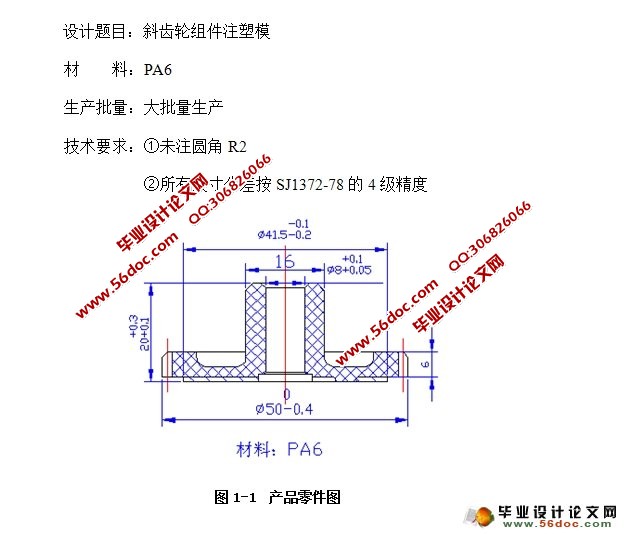
本设计题目为斜齿轮组件塑料注塑模,但对做毕业设计的毕业生有一定的设计意义,它概括了斜齿轮组件塑料零件的设计要求、内容及方向。通过对该零件模具的设计,进一步加强了设计者注塑模设计的基础,为设计更复杂的注塑模具做好了铺垫和吸取了更深刻的经验。
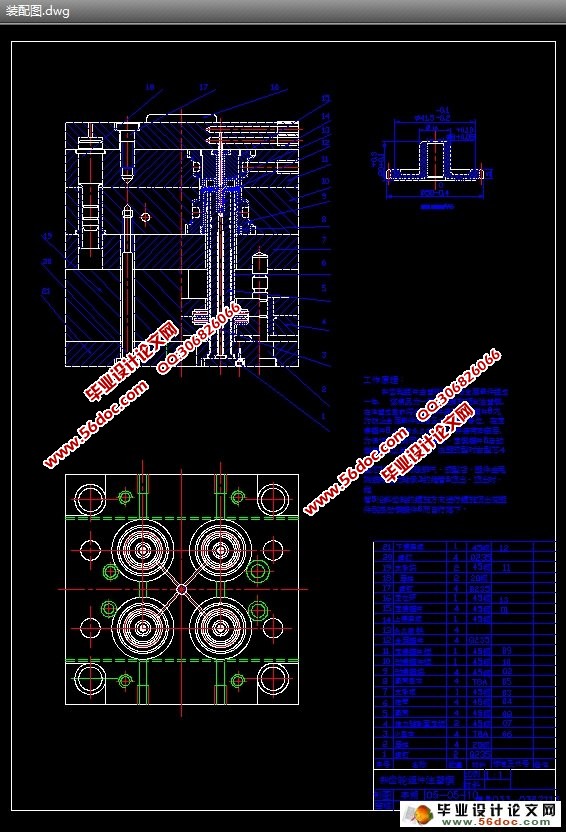
通过对方案的选择:从零件图上分析:该零件总体形状为带凸缘的斜齿轮组件,形状简单,结构合理且制件的壁厚均匀,在两边相交的部分也都设有圆弧过渡,在成型时塑料在模具型腔内流动阻力相对较小有利于制品的成型。本塑件是斜齿轮组件在齿轮外侧的齿槽与开模方向不一致且它们之间有一个螺旋的角度所以在脱模时必须考虑设计一个能在开模时随着开模过程的进行使塑件和型腔同时旋转一个角这样才能在开模时顺利把制件顶出,在本副模具的设计中,在顶管的尾部安装了推力轴承,在开模时顶杆顶动轴承盖及轴承座使推块上升,在上升的过程中,由于塑件及推块同时发生转动,直到塑件脱出型腔。这种机构脱模可靠,设计方便且在模具中占用空间较小,非常适合在本副模具中使用。相信不久本模具投入市场一定能带来很好的效益服务大众,服务社会。
关键词:塑料注塑模 斜齿轮组件 推力轴承 轴承盖 推块 型腔
The helical gear module note molds the design
Abstract
This design topic molds for the helical gear module note, but to the graduate which makes the graduation project has the certain design significance, it summarized the helical gear module plastic parts design request, the content and the direction. Through to this components mold design, further strengthened the designer note to mold the design foundation, for designed more complex casts the mold to complete the upholstery and to absorb a more profound experience.
Through to plan choice: Analyzes from the detail drawing: This components overall shape for belt flange helical gear module, shape simple, the structure reasonable also workpiece wall thickness is even, in the part which two intersects also all is equipped with the circular arc transition, when taking shape the plastic the flow resistance relative is slightly advantageous in the mold cavity to product taking shape. This models is the helical gear module with opens the norm in the gear flank socket to not to be inconsistent also them between has a spiral angle therefore in drawing of patterns time must consider designs to be able while operates the mold along with to open the mold process to carry on causes to model and the cavity revolves an angle to be able when operates the mold smoothly the workpiece to go against like this, in this mold design, has installed the thrust bearing in the top pipe rear part, when operates the mold the roof bar goes against moves the bearing cap and the bearing seat causes to push the block rise, in rise process, because models and pushes the block synchronize rotation, Until models the leaving cavity. This kind of organization drawing of patterns reliable, the design convenience also takes the space in the mold to be small, suits extremely in this mold uses. Can unquestionably bring very good benefit and serve the general public to invest the market while believing a mould soon, serve the society.
Key words :The plastic note molds Helical gear module Thrust bearing Bearing cap Pushes the block Cavity
插图清单
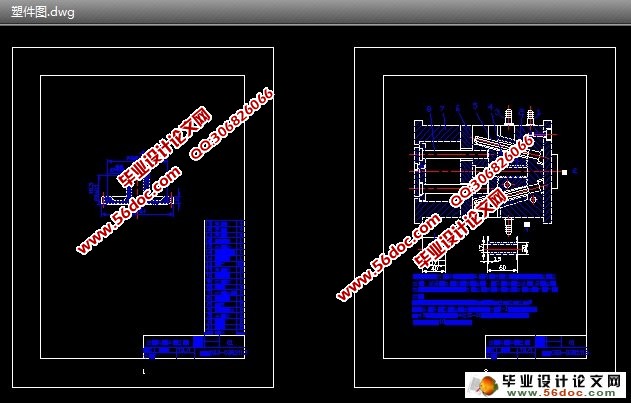
图1-1 产品零件图…………………………………………………………………5
图3-1 分型面………………………………………………………………………11
图3-2 型腔布置方式 ………………………………………………………………12
图3-3 半圆形分流道………………………………………………………………14
图3-4 凹模结构设计………………………………………………………………15
图3-5 凸模结构设计………………………………………………………………15
表格清单
表4-1 型腔、型芯工作尺寸计算………………………………………………16
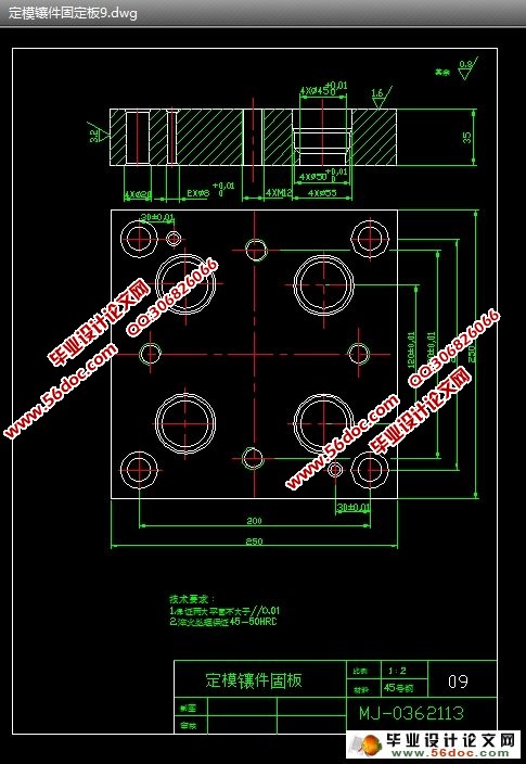
表10.1 定模镶件的加工工艺过程………………………………………………23
表10.2 动模镶件加工工艺过程 …………………………………………………25
目录
绪 论…………………………………………………………………… 1
第一章 任务来源及设计意义………………………………………… 5
1.1 设计任务来源……………………………………………………5
1.2 设计目的及意义…………………………………………………5
第二章 零件的工艺性分析……………………………………………7
2.1 塑件的原材料分析………………………………………………7
2.2 塑件的结构和尺寸精度及表面质量分析……………………………7
2.3 计算塑件的体积和质量…………………………………………8
2.4 塑件注塑工艺参数的确定………………………………………9
第三章 注塑模的结构设计……………………………………………11
3.1 分型面的选择…………………………………………………11
3.2 确定型腔的排列方式…………………………………………12
3.3 浇注系统设计…………………………………………………12
3.4 成型零件结构设计………………………………………………14
第四章 模具设计的有关计算…………………………………………15
4.1 型腔和型芯工作尺寸的计算………………………………………15
4.2 型腔侧壁厚度及底板厚度计算……………………………………16
第五章 脱模机构的设计………………………………………………17
第六章 模具加热与冷却系统的有关计算……………………………18
第七章 模具闭合高度的确定…………………………………………19
第八章 注塑机有关参数的校核………………………………………20
第九章 绘制模具总装图和非标准零件工作图………………………21
第十章 注塑模主要零件加工工艺规程的编制………………………22
10.1定模镶件固定板加工工艺过程……………………………………22
10.2定模座板加工工艺………………………………………………22
第十一章 模具的安装与调试…………………………………………25
11.1模具的安装………………………………………………………25
11.2模具的调试………………………………………………………25
设计总结…………………………………………………………………27
致谢………………………………………………………………………28
参考文献…………………………………………………………………29
|