玻璃升降器复合拉深模的设计
来源:56doc.com 资料编号:5D11495 资料等级:★★★★★ %E8%B5%84%E6%96%99%E7%BC%96%E5%8F%B7%EF%BC%9A5D11495
资料以网页介绍的为准,下载后不会有水印.资料仅供学习参考之用. 密 保 惠 帮助
资料介绍
玻璃升降器复合拉深模的设计(任务书,开题报告,外文翻译,中期报告,论文说明书20000字,CAD图纸12张)
摘 要
这份报告主要研究的是作为汽车零部件之一的活塞销的流动缺陷。在联合冷挤压制活塞销的工艺中,起皱就是一种流动缺陷,它是由死金属区引起的。具有这种缺陷的部件带有很明显的外部特征,特征是被一微小而且厚的块状物嵌入材料中,这种缺陷对保证尺寸精度和降低材料损失是不利的,活塞销的这种缺陷对于其强度和疲劳寿命也有不利的影响。因此,在工艺设计的早期预测并防止这种缺陷是非常重要的。防止其产生的最好方法就是通过控制材料流动来限制或减少死金属区。有限元模拟分析方法被应用于流动缺陷研究分析当中,这份研究报告提出了通过去除死金属区防止产生流动缺陷的新工艺方法——有限元分析法。将有限元分析的结果与实验结果做比较,结果表明有限元分析的结果与实验结果相符合。
关键词:流动缺陷;活塞销钉;材料流动控制;前后双向冷挤压;死金属区;有限元分析
ABSTRACT
A flow defect of a piston-pin for automobile parts are investigated in this study. In the combined cold extrusion of a piston-pin, a lappingdefect, which is a kind of flow defect, appears by the dead metal zone. This defect is evident in products with a small thickness to be piercedand is detrimental to dimensional accuracy and decrease of material loss. The flow defect that occurs in the piston-pin has bad effects onthe strength and the fatigue life of the piston-pin. Therefore, it is important to predict and prevent the defect in the early stage of processdesign. The best method that can prevent the flow defect is removing or reducing dead metal zone through the control of material flow.Finite element simulations are applied to analyze the flow defect. This study proposes new processes which can prevent the flow defect byremoving the dead metal zone. Then the results are compared with the results of experiments for verification. These FE simulation results
are in good agreement with the experimental results.
© 2003 Elsevier Science B.V. All rights reserved.
Keywords: Flow defect; Piston-pin; Material flow control; Forward–backward extrusion; Dead metal zone; FE simulation
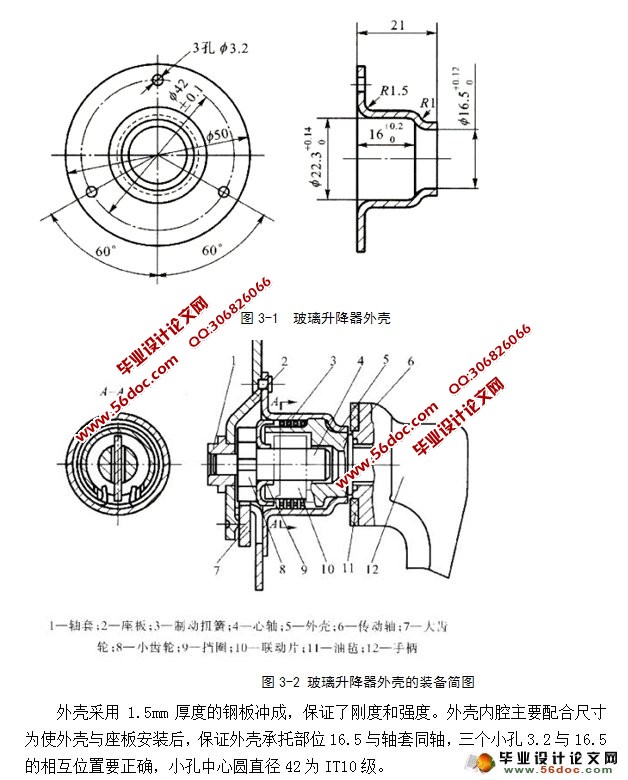
汽车车门玻璃升降器外壳件的形状、尺寸如图3-1所示,材料为08号钢板,板厚1.5mm,中批量生产,打算采用冲压生产,要求编制冲压工艺。
目 录
1 前言 5
1.1玻璃升降器的功用及拉深模的设计要求 5
2 冲裁工艺设计 7
2.1 冲裁工艺计算 7
2.1.1 工艺力和功的计算 7
2.1.2 压力机的选择 9
2.2 模具总体设计 9
2.2.1 模具类型的确定 10
2.2.2 操作方式的确定 10
2.2.3 定位、联接型式的确定 10
2.2.4 模具压力中心的确定 11
2.2.5 模具精度的确定 11
2.2.6模具闭合高度的初定 11
2.3 定位装置 11
2.4 卸料装置 11
2.4.1 卸料装置的选择 12
2.4.2 弹性元件的设计 12
2.5 落料凹凸模的设计 13
2.5.1 凸模结构的确定 13
2.5.2 凹模结构确定 14
2.5.3 凹凸模工作部分尺寸设计 14
2.5.4 凸凹模工作表面技术要求 16
2.5.5 凸凹模材料 16
2.6 导向装置 16
2.6.1 导向装置的选择 16
2.6.2 导向装置尺寸确定 16
2.7 模具其它主要零部件的设计 18
2.7.1 板料定位装置的设计 18
2.7.2螺栓和销钉的选用 19
3工艺方案选择 21
3.1 冲压件的工艺确定 21
3.1.1 冲压件的工艺分析 21
3.1.2 零件材料的分析 23
3.1.3确定工艺方案和模具形式 24
3.1.4落料尺寸的计算 25
3.2确定排样方案 26
3.2.1确定排样、裁板方案 26
3.3计算拉深次数 28
3.4拉深冲压力的计算 29
3.4.1落料过程 29
3.4.2、拉深过程 30
3.4.3成型过程 31
3.5冲压设备的选择 32
3.6 分析比较和确定工艺方案 33
3.6.1计算毛坯尺寸需先确定翻边前的半成品尺寸。 33
3.6.2计算拉深次数 34
3.6.3.确定工序的合并与工序顺序 35
4 主要工艺参数的计算 39
4.1 确定各中间工序尺寸 39
4.2计算各工序压力,选用压力机 40
4.3 模具设计 44
4.3.1 模具结构形式选择 44
4.3.2 卸料弹簧的选择 45
4.3.3 模具工作部分尺寸和公差计算 45
4.3.4模具其它零件的结构尺寸计算 47
4.4 工作原理: 48
4.4.1首次拉深 48
4.4.2 二次拉深 48
4.4.3 三次拉深 48
4.4.4.冲压工艺过程卡的编写 48
结论 50
致 谢 51
|