汽车稳定杆卡子冲压模具设计(开题报告,中期报告,外文文献翻译,论文说明书14500字,工序卡,CAD图9张)
摘 要
本文介绍的模具实例结构简单实用,使用方便可靠,首先根据工件图算工件的展开尺寸,在根据展开尺寸算该零件的压力中心,材料利用率,画排样图。根据零件的几何形状要求和尺寸的分析,采用复合模冲压,这样有利于提高生产效率,模具设计和制造也相对于简单。当所有的参数计算完后,对磨具的装配方案,对主要零件的设计和装配要求技术要求都进行了分析。
在设计过程中除了设计说明书外,还包括模具的装配图,非标准零件的零件图,工件的加工工艺卡片,工艺规程卡片,非标准零件的加工工艺过程卡片。
关键词:复合模 ;冲压 ;设计
Design of automobile stable bar clip stamping die
Abstract
This article introduced mold example structure simple and practical, convenient and reliable use, according to the dimension of workpiece is the workpiece, in the center of pressure parts according to the size, material utilization ratio, drawing layout. According to the analysis of the geometric shape and size requirements, the use of compound die stamping, which helps to improve the efficiency of production, mold design and manufacturing are also relative to the simple. When all of the parameter calculation is finished, assembly scheme to the tool, the main parts of the design and assembly requirements of the technical requirements are analyzed.
In the design process, in addition to the design specifications, but also including the mold assembly drawing, non-standard parts drawings, the workpiece card processing technology, process cards, process cards non standard parts.
Keywords: compound die punching; design;
目 录
1 绪 论 1
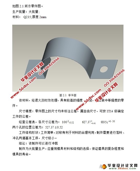
2 冲裁工件件的工艺分析 2
3 确定工艺方案及模具的结构形式 3
4 模具总体结构设计 4
4.1 模具类型的选择 4
4.2定位方式的选择 4
4.3卸料方式的选择 4
4.4导向方式的选择 4
5 模具设计工艺计算 5
5.1计算毛坯尺寸 5
5.2排样、计算条料宽度及步距的确定 5
5.2.1搭边值的确定 5
5.2.2条料宽度的确定 7
5.2.3 送料步距的确定 7
5.2.4 排样 8
5.2.5材料利用率的计算 8
6 冲裁力的计算 11
6.1计算冲裁力的公式 11
6.2 总冲裁力、卸料力、推料力、顶件力、弯曲力和总冲压力 11
6.2.1 总冲裁力 12
6.2.2 卸料力FQ的计算 13
6.2.3推件力FQ1的计算 13
6.2.4顶件力FQ2的计算 13
6.2.5总的冲压力的计算 13
7 模具压力中心与计算 14
8 冲裁模间隙的确定 15
9 冲裁凸模、凹模刃口尺寸的计算 17
9.1凸、凹模刃口尺寸计算的基本原则 17
9.2凸、凹模刃口尺寸的计算 18
9.3计算凸、凹模刃口的尺寸的计算公式 19
9.4冲裁刃口高度 21
9.5弯曲部分刃口尺寸的计算 21
9.5.1最小相对弯曲半径rmin/t 21
9.5.2弯曲部分工作尺寸的计算 22
10 主要零部件的设计 26
10.1 工作零件的结构设计 26
10.1.1凸凹模的设计 26
10.1.2外形凸模的设计 26
10.1.3内孔凸模设计 27
10.1.4弯曲凸模的设计 27
10.2卸料部分的设计 27
10.2.1卸料板的设计 27
10.2.2卸料弹簧的设计 28
10.3定位零件的设计 29
10.4模架及其它零件的设计 30
10.4.1上下模座 30
10.4.2模柄 30
10.4.3模具的闭合高度 31
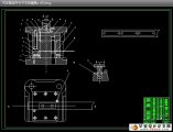
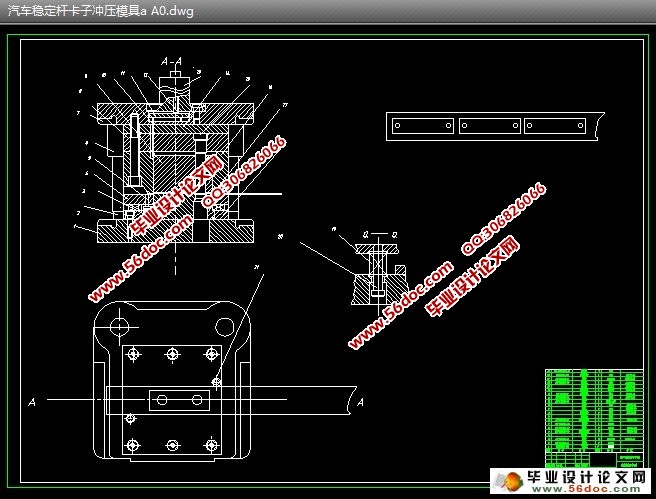
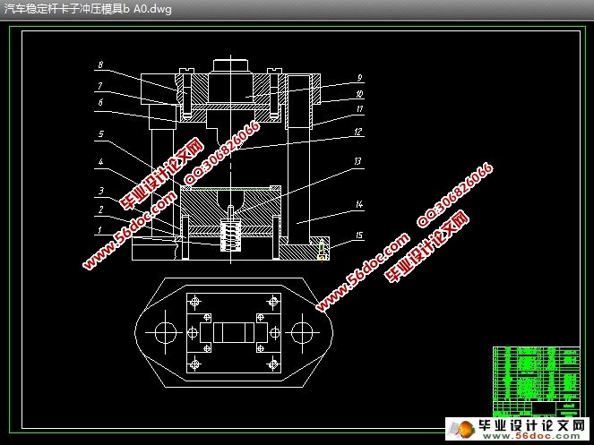
11 模具总装图 32
12 压力机的选择 33
总 结 34
致谢 35
参考文献 36
|