焊片冲孔落料弯曲模设计(含CAD零件图装配图)
来源:56doc.com 资料编号:5D11668 资料等级:★★★★★ %E8%B5%84%E6%96%99%E7%BC%96%E5%8F%B7%EF%BC%9A5D11668
资料以网页介绍的为准,下载后不会有水印.资料仅供学习参考之用. 密 保 惠 帮助
资料介绍
焊片冲孔落料弯曲模设计(含CAD零件图装配图)(任务书,中期检查表,论文说明书10000字,工序卡,工艺过程卡,CAD图19张)
摘 要
本设计题目为中焊片冲孔落料弯曲模设计。通过对该零件模具的设计,进一步加强了设计者冲孔落料弯曲模设计的基础知识,为设计更复杂的冲压模具做好了铺垫和吸取了更深刻的经验。
本设计运用冲压成型工艺及模具设计的基础知识,介绍了模具设计时要注意的要点,并较多的考虑了模具结构的调整性、易更换性及模具成本。从控制制件尺寸精度出发,对外壳冲孔切边模的各主要尺寸进行了理论计算,以确定各工作零件的尺寸,从模具设计到零部件的加工工艺以及装配工艺等进行详细的阐述,并应用CAD进行各重要零件的设计。
关键词:冲孔,落料,弯曲模 工艺分析 模具结构
The design of punching,bending and blanking die of Soldering Flake
Abstract
The design the topic for the Design of the Trimming Die punching shell. The designer’s foundation knowledge is reinforced and is able to design more complex press die through the design.
The design of the use of punch forming process and die design of the basic knowledge on the mold design to the main points of attention and more consideration of the mold structure, and easy to replace and the cost of mold. Size precision parts from the control point on the shell punching die trimming the size of all the major theoretical calculations carried out to determine the size of the working parts, the parts from the mold design process and the assembly process in detail, etc., and the application of CAD for the design of the important parts.
Key words: Punch holes, Falls the material ,Bending die, process analysis , die structure
目 录
1 绪论……………………………………………………………………………1
1.1我国塑料模具的发展现状…………………………………………………1
1.2 国外模具的现状和发展趋势……………………………………………2
2 制件的工艺性分析……………………………………………………………5
3 艺方案的确定…………………………………………………………………6
3.1排样设计……………………………………………………………………6
3.2计算凸,凹模刃口尺寸……………………………………………………11
3.2.1冲孔φ8.5凸凹模刃口尺寸的计算……………………………………6
3.2.2外形凸凹模刃口尺寸的计算……………………………………………7
4 弯曲工艺计算…………………………………………………………………11
4.1凸模圆角半径………………………………………………………………11
4.2凹模圆角半径………………………………………………………………11
4.3凹模工作部分的设计计算…………………………………………………17
4.4凸凹模间隙…………………………………………………………………11
4.5凸凹模模向尺寸及其公差…………………………………………………11
4.6弯曲回弹值的计算…………………………………………………………11
4.7弯曲力的计算………………………………………………………………12
4.8冲压力的计算………………………………………………………………12
4.9压力中心的计算……………………………………………………………13
5 模具总体设……………………………………………………………………14
6 模具主要零部件的结构设计…………………………………………………16
6.1落料凸模的结构设计………………………………………………………16
6.2冲孔φ8.5凸模的设计……………………………………………………16
6.3凸模的长度根据结构上的确定…………………………………………16
6.4凸凹模的结构设计………………………………………………………16
7 橡皮的选用和计算……………………………………………………………17
7.1橡皮的平面尺寸…………………………………………………………17
7.2橡皮的高度………………………………………………………………17
7.2.1橡皮最大压缩量…………………………………………………………17
7.2.3压缩工作行程……………………………………………………………17
7.2.4高度校核…………………………………………………………………17
7.2.5高度范围…………………………………………………………………17
8 模架的设计………………………………………………………………………20
9 冲压设备的选择…………………………………………………………………21
10 模具设计总结……………………………………………………………………22
致谢……………………………………………………………………………………26
参考文献 ……………………………………………………………………………27
插图清单
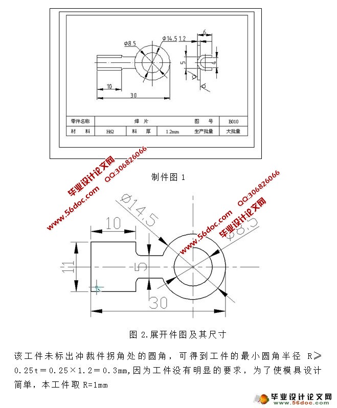
图1 焊片制件图 ……………………………………………………………4
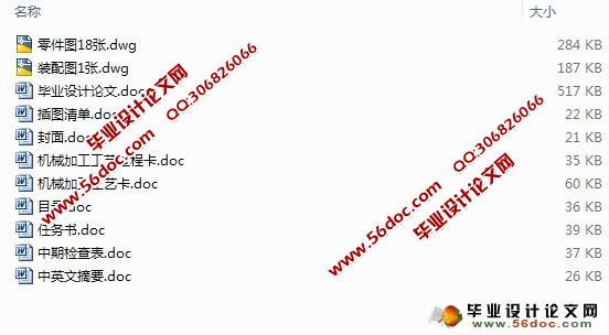
图2展开件图及其尺寸………………………………………………………5
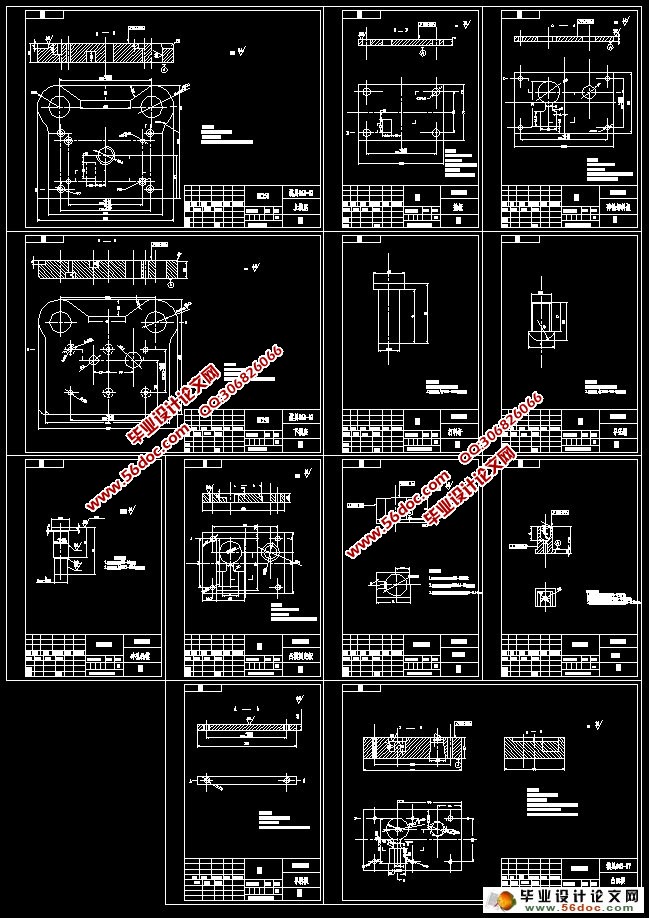
图3落料凸模 ………………………………………………………………8
图4落料弯曲凸凹模…………………………………………………………9
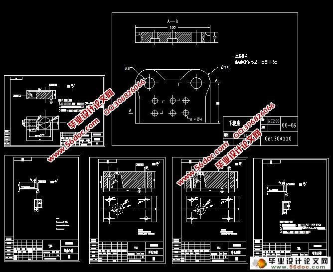
图5凹模形状尺寸 …………………………………………………………10
图6 冲孔凸模示意图 ……………………………………………………13
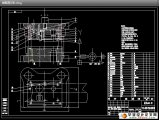
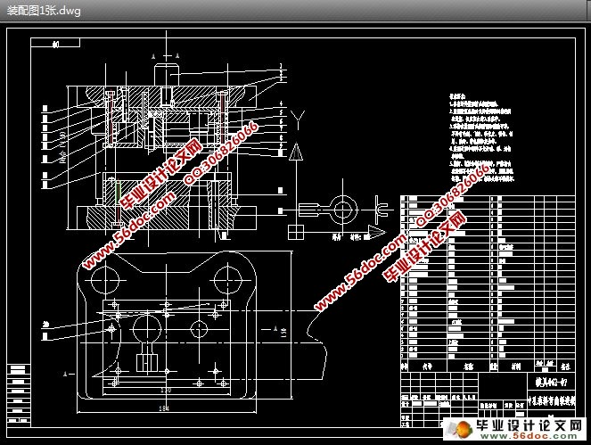
图6模具整体装配 …………………………………………………………15
图7弹性橡皮插图 …………………………………………………………18
图8模架 ……………………………………………………………………20
|