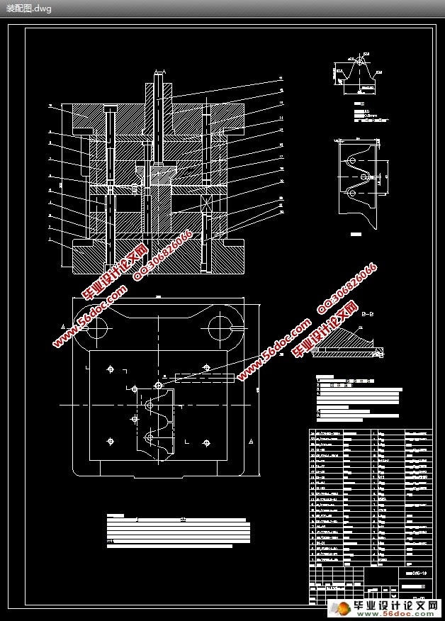
支板冲压成形工艺复合模具设计(含CAD零件图装配图)(任务书,中期检查表,论文说明书16000字,工序卡,CAD图17张)
摘 要:本设计题目为复合模具设计,体现了典型复合模具设计的要求,内容与方向。通过工艺分析,工艺方案的确定,确定了模具设计的方向,对毛坯尺寸的确定,计算冲裁力,来计算压力中心,选择压力机和压力机的吨位。
本设计运用了冲裁工艺及模具设计的基础知识。首先,分析了板材的性能要求,为选去模具的类型做了准备,同时,也为凸,凹模的材料有了依据。后分析冲裁件的特征,确定了模具设计参数,选择其他零件及卸料装置。也为凸,凹模尺寸的计算有了根据。还有零件的加工工艺。
本设计运用冲压成形工艺及模具设计的基础知识,首先分析了冲裁件的冲压工艺性,为确定冲裁工艺方案做好了准备;然后计算冲裁力和模具刃口尺寸,便于选取压力机及确定工作零件的尺寸和结构;最后分析了制件的特征,确定模具的设计参数、设计要点及推件装置的选取。
本冲裁件上孔为规则形状的孔,为了便于冲孔凸模的加工,在设计时把冲孔凸模设计成台阶式。为了方便制件的取出,本副模具采用倒装结构形式,同时,为了简化模具结构采用弹性推件装置。
关键词: 复合模 排样 凸模 凹模 凸凹模
The pressworking forming process and mold design of protrude board
Abstract:This design topic designs for The piercing die design of the dunnage backup plate, body now typical model The piercing die design of request, contents and direction.Pass the craft analysis, the craft project really settles, making sure the direction of The piercing die design, really settling to the blank product size, computing to the blanking pressure, compute the pressure center, choose the tonnage of the pressure machine and the pressure machine.
This design made use of to hurtle foundation knowledge of blanking craft and The piercing die design. First, Analyzed the function request of the plank material, did preparation for the type that chooses to the die, is also convex, in the meantime, the material of punch and cavitydie had a basis.Analyze to hurtle a characteristic of cut the piece behind, make sure the molding tool design parameter, choose other spare partses and unload to anticipate device.Is also convex, the calculation of the cave mold size had a basis.Still there is spare parts to process a craft.
The use of the design process and die stamping forming the basis of design knowledge and analysis of the first blanking of the stamping process, to determine blanking of the programme prepared for and then calculating punching power and size Die Cutting Edge, For selected press and determine the size and structure of parts of the last parts of the characteristics of the design parameters established mold, design features and pushing the select pieces of equipment.
Blanking of the rules on the shape of the hole, in order to facilitate the processing punch punching, punching in the design of the punch designed as a step processing. To facilitate the removal of parts, the Vice-use flip-die structure, at the same time, in order to simplify the structure adopt a flexible mold push pieces of equipment.
Keywords: The piercing die blank lagout punch cavitydie punch and die
制件的总体分析
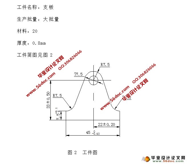
该零件的外形复杂程度一般,是由圆弧和直线组成的。由于冲裁件的内外形所能达到的经济精度为IT11~IT14级,孔中心与边缘的距离尺寸公差为±0.5mm。将以上精度与零件的精度要求相比较,可得到该零件的精度要求能够在冲裁加工中得到保证,其它尺寸标注,生产批量等情况,也均符合冲裁的工艺要求。
工艺性:支板属于中等尺寸零件,料厚0.8mm,外形复杂程度一般,尺寸精度要求如图示,零件材料为20钢,是优质碳素结构钢,具有良好的塑性,市场上也容易得到这种材料,价格适中。
因此零件外形可采用落料工艺获得。
冲孔的工艺性:φ7.5mm 的孔,尺寸精度要求一般,可采用冲孔。
此工件只有外形落料和冲孔两个工序。
由以上分析可知,图示零件具有比较好的冲压工艺性,适合冲压生产。
目 录
1 绪 论……………………………………………………………………………1
1.1冲压与冲压模具的概念………………………………………………………… 1
1.2冲压的特点及应用……………………………………………………………… 1
1.2.1冲压生产的特点………………………………………………………………1
1.2.2冲压生产的应用…………………………………………………………………2
1.3冲压技术的现状及发展方向……………………………………………………4
2 支板的工艺性分析………………………………………………………………8
3 工艺方案的确定…………………………………………………………………10
4 主要工艺参数计算………………………………………………………………11
4.1 排样的设计与计算……………………………………………………………11
4.1.1确定搭边与搭肩值………………………………………………………………12
4.1.2 计算送料步距和条料的宽度……………………………………………… 13
4.1.3计算材料的利用率………………………………………………………………13
4.2冲压力的计算并初步选取压力机的吨位………………………………………13
4.3 压力机的公称压力的确定………………………………………………………16
4.4压力中心的确定…………………………………………………………………17
4.5 工作部分的尺寸计算……………………………………………………………18
4.5.1计算凸凹模工作部分的尺寸并确定其公差……………………………………18
4.5.2外形落料凸模、凹模刃口尺寸的计算…………………………………………21
5 模具总体设计………………………………………………………………………23
5.1 模具类型的选择…………………………………………………………………23
5.2 定位方式的选择…………………………………………………………………23
5.3 导向方式的选择…………………………………………………………………23
5.4 卸料方式的选择…………………………………………………………………23
6 模具主要零部件的设计……………………………………………………………24
6.1工作零件的结构设计…………………………………………………………24
6.1.1 凹模的设计……………………………………………………………………24
6.1.2 冲孔凸模的设计………………………………………………………………26
6.1.3凸凹模的结构设计………………………………………………………………28
6.2定位零件的设计…………………………………………………………………29
6.2.1 固定挡料销的设计与标准化…………………………………………………29
6.2.2 导料销的设计与标准化………………………………………………………29
6.2.3始用挡料销…………………………………………………………………… 30
6.3 导向装置的设计…………………………………………………………………30
6.4 卸料装置的设计…………………………………………………………………31
6.5 连接与固定装置的设计…………………………………………………………32
6.5.1模柄的设计………………………………………………………………………32
6.5.2 固定板的设计…………………………………………………………………32
6.5.3 垫板的设计……………………………………………………………………33
6.5.4 螺钉与销钉的设计……………………………………………………………33
6.5.5 卸料板的设计…………………………………………………………………33
6.6 模架及组成零件的确定………………………………………………………34
6.6.1 模架的选用……………………………………………………………………34
6.6.2 模座的确定……………………………………………………………………34
7压力机有关参数的校核及模具闭合高度…………………………………………35
8绘制模具总装图和非标零件工作图………………………………………………36
9模具主要零件加工工艺规程的编制………………………………………………37
结束语…………………………………………………………………………………41
致谢 …………………………………………………………………………………42
参考文献………………………………………………………………………………44
插图清单
图1 冲压零件质量的影响因素……………………………………………………1
图2 工件图…………………………………………………………………………8
图3 排样图…………………………………………………………………………11
图4 压力中心………………………………………………………………………17
图5 落料凹模的结构简图…………………………………………………………24
图6 冲孔凸模的结构形式……………………………………………………… 26
图7 凸凹模的结构简图………………………………………………………… 28
图8 固定挡料销的结构……………………………………………………………29
图9 导料销的设计…………………………………………………………………30
插表清单
表1 最小搭边值……………………………………………………………………12
表2 卸料力、推件力、顶件力系数………………………………………………15
表3 较小间隙的冲裁模具初始双面间隙………………………………………… 18
表4 简单形状冲裁件(圆形、方形件)冲裁时的δ凸、δ凹………………………19
表5 磨损系数x…………………………………………………………………… 20
表6 机械加工工艺过程卡………………………………………………………… 37
表7 机械加工工艺过程卡………………………………………………………… 39
|


