推动架零件的机械加工工艺规程和φ16通孔底孔钻夹具(含CAD图)(任务书,文献综述,设计说明书16600字,CAD图纸8张)
摘要
在现代生产中,机床夹具作为机床的一部分,已经成为一种不可缺少的机械加工技术和设备。工件生产批量比较大时,另外我们要考虑工件的加工精度的生产力、生产率和经济问题,所以经常使用专为某一工件的装夹零件的专用夹具进行装夹。这时不需划线和找正,只需将工件放到夹具中,即可确定工件与机床及刀具之间的位置,并将工件夹紧。
专用夹具是对某一工作过程的要求和制造夹具设计过程的一部分。其特点是针对性极强,没有通用性。在相对稳定的生产,大批量生产,常用各种专用夹具,可获得较高的生产率和加工精度。专用夹具在当今社会得到了广泛的应用,为人类发展起到了巨大的贡献。尤其是在制造业的应用,特别是在一些航空航天、精密仪器,仪表的制造中人们常常使用夹具进行工件的定位装夹,以便平稳的进行加工。
分析零件的工艺性能,考虑零件的作用及使用寿命,确定产品的市场需求、生产类型。计算工序尺寸及毛坯尺寸并确定切削用量及基本工时。工艺路线的选择突显其重要性,包括基准面的确定、材质的择取、刀具的选择等。综合考虑各种因素叠加对加工工艺的影响,采取适度原则,保证加工精度,平稳加工。
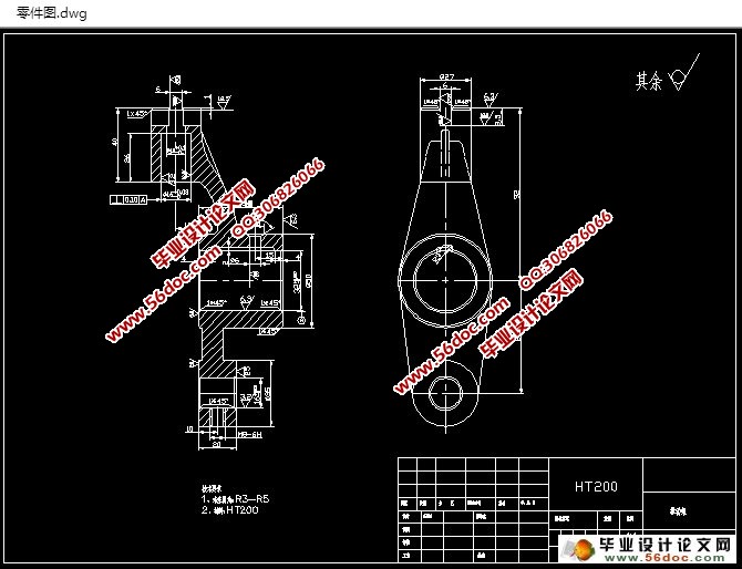
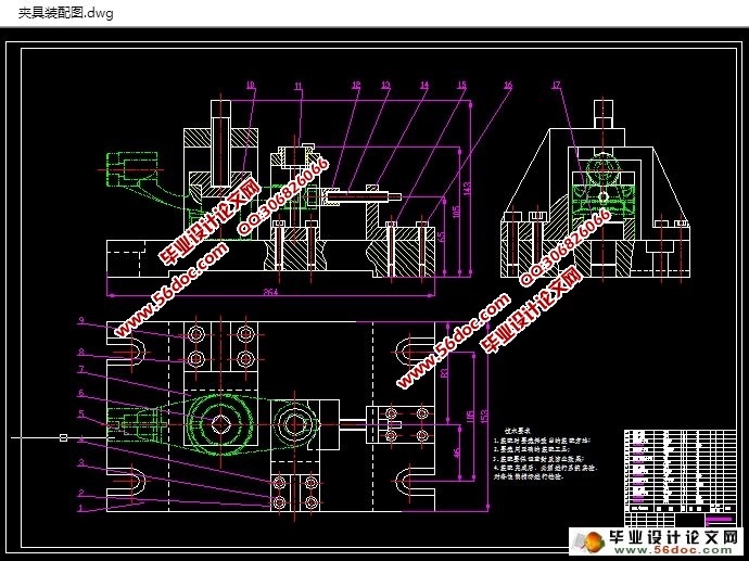
本设计对一个给定的设计部分是推动架,它的主要作用是从电机的旋转运动通过偏心杠杆推动架左右摆动轴线的为了实现工作台自动进给。对零件进行充分分析的基础上,确定过程的基础上,对加工过程卡的制备,加工工艺卡片,绘制装配图和零件图。本次设计的夹具是在钻床上加工Ф16孔,设计合理,操作简便,为零件的加工提供强有力的保障。
毕业设计是总结我大学期间所见所闻所学的一次重要成果的体现,我通过计算其尺寸设计出V型块、夹具体、定位座、压紧座、钻模座等尺寸,利用AutoCAD和Pro\E对产品进行分析二位和三维的总装图和零件图。
关键词:机床夹具; 专用夹具; 推动架; 基准; 钻床
Abstract
In modern production, jigs and fixtures, as part of the machining tool has become an indispensable technology and equipment. Workpiece production volume is large, in addition to considering the accuracy of the workpiece outside, we also need to take into account productivity and economic issues, so often using special fixtures designed specifically for a particular part of a process designed to make clamping workpieces. Then without scoring and alignment, simply place the workpiece fixture, you can determine the position of the workpiece and the cutting tool and the machine between the clamp and the workpiece.
Special fixture is part of a working process of fixture design requirements and manufacturing processes. Its characteristics are highly targeted, not universal. In the relatively stable production, mass production, used a variety of special fixtures, can obtain higher productivity and precision. Dedicated fixture in today's society has been widely used for human development has played a huge contribution. Especially in manufacturing applications, especially in the aerospace, precision instruments, meters, people often use manufacturing workpiece clamping jig positioning for smooth processing.
Analyze the technological capability of the parts, consider the function and service life of the parts, determine the market demand and production type of the product.. Calculate the size of the working procedure and the size of the blank and determine the amount of cutting and the basic working hours.. Highlight the importance of selection process, including the determination of the datum plane, the choice of tool material selection, etc.. The effect of various factors on the processing technology is considered, and the appropriate principle is adopted to guarantee the machining accuracy and smooth machining..
The design of a given design is to promote the shelf parts, and its main role is coming from the rotary motion of the motor through the eccentric lever so that pushing the swing frame around its axis in order to achieve automatic feeding table. In the full analysis of the parts based on the benchmarking process each step, the preparation of the machining process card, card manufacturing processes, assembly drawing and parts diagram. This fixture design is machined on drilling holes Ф16, reasonable design, simple operation, and provide a strong guarantee for the part.
Analysis of the product of two and three dimensional assembly drawing and parts drawing using AutoCAD and Pro\E graduation design is the summary of my university period saw a major achievement reflected through calculate the size to design the V type block, a clamping concrete, positioning seat, a clamping seat, drilling die block size.
Keywords: jigs; special fixtures; pushing frame; benchmarks; drilling
2.1.1 零件的作用
操纵杆支架是本次毕业设计所研究的零件,由于,其主要功能是将电动机通过围绕摆动轴线的偏心杆框架驱动的旋转运动,以实现自动送料台。
2.1.2 零件的工艺性能
零件图是制造零件的主要技术基础,设计过程之前,首先要仔细分析技术,通过对部分功能的理解和精密零件等重要技术要求的工作条件,为了更好的把握和技术关键的结构特点。在零件图上,必须有完整的表现形态来看,段与段,还应标注外形尺寸稳定性,合理的精度和技术要求,零件和材料,热处理,表面处理等级,特殊检查及其他要求。在对零件图要求有了一定了解后,进行了以下几个方面的一般性分析:
1、加工零件主要表面的要求及保证的方法;
2、怎么样达到重要的技术要求及保证方法;
3、零件的表面位置尺寸标注。
目 录
第一章绪论 1
1.1 机床夹具的功能和作用 1
1.1.1 机床夹具的功能 1
1.1.2 机床夹具的作用 1
1.2 机床夹具的组成 2
1.3 机床夹具的分类及设计要求 3
1.3.1 机床夹具的分类 3
1.3.2 机床夹具的设计要求 4
1.4 机床夹具的现状及发展方向 5
1.5 课题设计的价值 6
第二章操纵杆支架机械加工工艺规程设计 8
2.1 零件的工艺分析及生产类型的确定 8
2.1.1 零件的作用 8
2.1.2 零件的工艺性能 8
2.1.3 零件的加工表面分析 9
2.1.4 零件生产类型的确定 9
2.2 零件工艺规程设计 9
2.2.1 零件制造形式的确定 10
2.2.2 基准的选择 10
2.3 制定加工工艺路线 11
2.4 选择加工设备及刀具、夹具、量具 13
2.5 机械加工余量,工序尺寸及毛坯尺寸的确定 13
2.6确定切削用量及基本工时 13
第三章专用夹具的设计 21
3.1 问题的提出 21
3.2 夹具的设计要求 21
3.3 夹具设计 21
3.3.1 定位方案的确定 21
3.3.2 定位元件的确定 22
3.3.3 夹紧装置的确定 23
3.3.4 夹具体的确定 24
3.3.5 钻削力的确定 24
3.2.6 定位误差分析 25
第四章结论 26
参考文献 27
致谢 28
附录 29
|