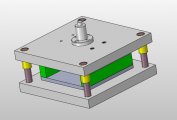
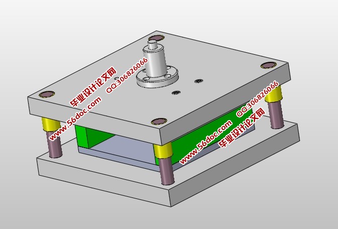
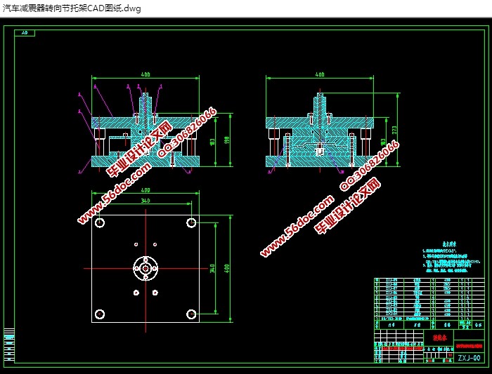
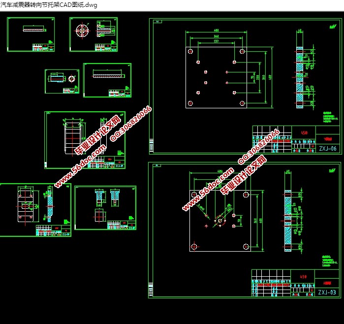
汽车减震器转向节托架冲压模具(含CAD图,SolidWorks三维图)(论文说明书10000字,CAD图纸11张,SolidWorks三维图)
摘要:本文为汽车减震器转向节托架冲压模具设计。设计中运用冲压模具设计与制造的知识及CAD应用的知识,包括工艺分析、冲压方案的确定、模具结构的设计、参数的计算、也包含了冲裁力计算,定距方法,冲裁间隙选择,压力中心计算的设计要点以及运用CAD画零件图和装配图。
本文介绍的模具实例简单实用,使用方便可靠,根据零件的几何形状要求和尺寸的分析,采用冲压模冲压,这样有利于提高效率,模具设计和制造也相对简单。
关键词:托架;冲压模具;设计
The Knuckle bracket stamping die design for automotive shock absorber steering
Abstract:This article makes compound stamping die design . Used in the design of stamping die design and manufacture of knowledge, and the application of CAD, including process analysis, the scheme determination of stamping, die structure design, parameter calculation, also includes cutting force calculation distance method of blanking clearance choise ,design key points of pressuer center calculation and the use of CAD drawing parts drawing and assembly drawing. Examples in this paper.
the mold is simple and practical, easy to use and reliable, according to the requirements of the parts geometric shapes and dimensions of analysis, USES the compound die stamping, so to improve efficiency, mold design and manufacturing is relatively simple.
Key words: compound die; Stamping; design
工艺分析
生产批量:中批量;
材料:钢板;
材料厚度:4mm;
零件结构
零件结构形状相对简单,整体是一个矩形长度213mm,宽度98.3mm,厚度4mm,中间有方形通孔48X24MM,根据该零件形状来分析,该零件的结构满足冲裁要求。
目 录
绪 论 1
1. 工艺分析 2
1.1材料分析 2
1.2零件结构 2
1.3尺寸精度 2
2. 冲压工艺方案的确定 4
2.1冲裁工艺方案的确定 4
2.2冲裁工艺方法的确定 4
3. 冲压模具总体结构设计 6
3.1 模具类型 6
3.2 操作与定位方式 6
3.3 卸料与出件方式 6
3.4 模架类型及精度 6
4. 工艺参数计算 7
4.1 搭边值的确定 7
4.2材料利用率的计算 9
4.3冲压力的计算 10
4.2.1 总冲裁力的计算 10
4.2.2 压力中心的确定 11
5. 刃口尺寸计算 13
5.1冲裁间隙的确定 13
5.2刃口尺寸的计算及依据和法则 13
6. 模具的总体设计 17
6.1凹模设计 18
6.2凸模设计 19
6.2.1 凸模结构的确定 19
6.2.2 凸模高度的确定 19
6.2.3 凸模材料的确定 20
6.2.4 凸模精度的确定 20
7. 模具的装配 22
7.1 模具的装配过程可归纳为 23
7.2 装配的技术要求有 24
7.3 选择冲压设备 24
7.4 试模 24
8. 结论 25
参考文献 26
致谢 27
|