轻型卡车加强筋弯曲模设计(含CAD零件装配图)(论文说明书15000字,CAD图纸12张)
DESIGN OF BENDING DIE FOR REINFORCING RID OF LIGHT TRUCK
摘要
目前,在我国日常的工业生产中轻型卡车的使用范围很广,但在生产轻型卡车时,车厢加强筋使用量很大,并且在折弯机上加工时会出现弯曲困难,加工时间过长,损耗弯折机寿命等问题,对轻型卡车车厢的加强筋弯曲模进行设计,可缩短加强筋弯曲的时间,使成型效果更好,而且降低成本,有助于加快经济发展。因此本设计对现实生产生活有着重要意义。
首先分析了制造轻型卡车加强筋的材料的工艺性并确定了合适的尺寸,然后计算弯曲部分的最小弯曲半径,弯曲弹复角以及坯料的精确长度。最后,根据计算结果确定所要运用的弯曲工艺方案。从上述力的分析中,计算材料的弯曲应力并选择合适压力机。计算凹凸模的外形尺寸并确定其制造和组装精度,接着确定固定板和上下模座的尺寸。选择合适零件,如:顶件板,定位板和弹顶器等,并确定顶件板尺寸。基于上述数据最终确定了压力机的型号。最后,根据以上计算结果使用AUTOCAD绘图软件绘制模具的总装配图和部分重要零件的零件图。
关键词 轻型卡车;加强筋;弯曲模;模具设计
Abstract
At present, Light trucks are widely used in China's daily industrial production, but the amount of reinforcing rib in light truck carriage is large, bending on the bending machine is time-consuming and laborious, and losses the service life of the bending machine. the design of the bending die of reinforcing rib in light truck carriage can improve the forming efficiency and forming effect of reinforcing rib, and the cost is low, which is helpful to accelerate the economic development. Therefore, the research of this topic is of great significance to actual production and life.
In this paper, the process analysis was carried out according to the material and size of the light truck ribs. The minimum bending radius and the bending complex radius of the bending part were determined and the length of the blank was calculated. Finally, determine the bending process plan. By analyzing the above forces, the bending stress of the material is calculated and a suitable press is selected. Calculate the external dimensions of the concave-convex mold and determine its manufacturing and assembly accuracy, and then determine the dimensions of the fixed plate and upper and lower mold seats. Select suitable parts, such as top plate, locating plate and ejector, and determine the size of top plate.Finally, the model of the press was determined based on the above data.Finally, use AUTOCAD software to draw the assembly drawings of the mold and the parts drawings of important parts such as male and female molds. The design of stiffener bending die was finally completed.
Keywords light truck rib reinforcement bending die die design
本课题主要的设计内容为:
1、分析折弯机弯曲作业时的弯曲变形特点,确定合理的模具设计方案;
2、综合轻型卡车实际情况和模具设计的具体要求确定凸凹模的具体尺寸;
3、选择正确的模具材料及合适的热处理方法;
4、由于弯曲过程比较复杂,存在弯曲应力、弯曲回弹等问题,因此要通过计算校核确定设计正确;
5、绘制弯曲模装配图及部分零件图(包括凸凹模、卸料板等);
2零件的工艺性分析和实验方案论证
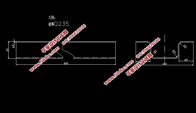
本课题为轻型卡车加强筋弯曲模的设计,设计的零件如图2-1所示,其中四个内圆角r1=r2=r3=r4=5mm,生产纲领则为大批量生产。材料为Q235。
2.1零件的工艺性分析
2.1.1零件材料的选择
本文所设计的轻型卡车弯曲模加强筋的零件材料为Q235(以前称为A3刚,现已不使用),Q235钢属于碳素结构钢,是GB700-79标准中规定的甲类钢,甲类钢能够保证零件的机械性能; 乙类钢则保证保证材料的化学成份。如今GB700-79 已经被GB700-88 取代了。Q235钢塑性加工性能好,其主要机械性能如下:Q235钢材料状态为未退火状态,屈服强度σs=253MPa,抗剪强度τ=304~373MPa,抗拉强度σb=432~461MPa,延伸率δ10=21~25%[ ]。
2.1.2零件结构
由图2-1可看出加工零件较为简单,不需要冲孔,只需将板料进行弯曲即可。
2.1.3最小许可弯曲半径
最小许可弯曲半径是指在材料不发生破坏的情况下弯曲半径的最小值。将板材弯曲成型时,弯曲件的圆角半径应当适中。半径过大,难以保证弯曲件的精度;半径过小,则板材易产生裂纹。因此在进行弯曲作业时需要计算最小弯曲半径。
目 录
摘要 I
Abstract II
1 绪论 1
1.1 设计的目的及意义 1
1.2 国内外的发展现状 1
1.2.1 模具发展现状 1
1.2.3 主要设计内容 3
2零件的工艺性分析和实验方案论证 4
2.1零件的工艺性分析 4
2.1.1零件材料的选择 4
2.1.2零件结构 4
2.1.3最小许可弯曲半径 4
2.1.4 弯曲件的直边高度 5
2.1.5 对称性工件的圆角半径的设置 5
2.1.6 零件尺寸的精度 5
2.1.7 零件弯曲时的回弹 6
2.1.8 弯曲件展开长度的计算 6
2.2 弯曲工艺方案的确定及弯曲模结构的设计原则 7
2.2.1 弯曲工艺方案的论证 7
2.2.2 弯曲模结构设计原则 8
3 弯曲力的计算和压力机的选用 9
3.1弯曲力的计算 9
3.1.1 第一阶段自由弯曲力的计算 9
3.1.2 第二阶段校正力的计算 10
3.1.3 顶件力的计算 10
3.2 弯曲时压力机压力的确定和压力机型号的初步确定 11
3.2.1 弯曲时压力机压力的确定 11
3.2.2 压力机型号的确定 11
4 弯曲凸、凹模设计 14
4.1 弯曲凸、凹模的间隙确定 14
4.2 弯曲模工作部分尺寸计算 15
4.2.1 凸凹模宽度尺寸的计算 15
4.2.2 凸、凹模的圆角半径确定 16
4.3 凹模外形尺寸设计 16
4.4 凹模强度校核 17
4.5 凸模设计 18
4.6 凸模强度校核 18
4.7 弯曲件凸、凹模深度及凸模两侧部分尺寸的确定 19
4.8 凸、凹模的固定 20
4.9 弯曲件凸、凹模材料的选用及热处理 20
5.1 固定板的设计计算 24
5.1.1凹模固定板的设计 24
5.1.2 凸模固定板的设计 25
5.2 凹模垫板 26
5.3 顶件装置设计 27
5.4 弯曲模下模座的设计 28
5.5 定位零件的设计计算 29
5.6 弹性元件的设计计算 30
5.8 模具总装配图 33
6 压力机的最终确定 34
结论 35
致谢 36
参考文献 37
|
