外基座冲压工艺与模具设计(含UG三维图)(任务书,开题报告,外文翻译,论文说明书13000字,UG三维图,PDF二维图)
摘 要
本文进行了外基座的模具设计。首先对零件进行了工艺分析,根据分析结果确定所需模具采用多工位级进模的形式。结合零件的外形和工艺要求进行了排样设计,即设计出了模具的各个工位的工序以及工序的分布情况。该零件的加工过程一共需要九个工位,依次为:冲切侧刃、冲切口用工艺孔、切口、空工位、拉深、整形、冲底孔、导正、落料翻边。对零件冲压加工过程中的毛坯尺寸及冲压力进行了计算,通过计算结果设计选择出模具的各个零部件,并借助计算机辅助设计软件Auto CAD和UG对所设计出的模具进行了二维和三维建模,使设计结果能更直观的表现出来。在三维建模的基础上利用DERORM对拉深工位进行了工作过程的模拟,模拟结果良好,制件尺寸达到要求,各部分变形均匀,均未出现拉裂、起皱等明显缺陷。除了单纯地进行了模具结构的设计,还对整套模具的制造成本进行了估算,所得结果对于实际生产具有重要的指导意义。
关键词:外基座;多工位级进模;拉深;模具成本
Abstract
Multi-position progressive die is a practical stamping die with high efficiency, high speed, high quality and long life. It is suitable for mass production of small and complex three-dimensional parts and is widely used in practical production. The part that needs die design in this paper is an outer base. Firstly, the process analysis of the parts is carried out, and the multi-position progressive die is determined according to the analysis results. The layout design was carried out according to the shape and process requirements of the parts, i. e. the process of each working position of the die and the distribution of the process were designed. The processing process of this part requires nine workstations, in turn: punching side edge, punching hole, cutting, empty workstation, drawing, shaping, punching bottom hole, straightening, blanking flanging.The blank size and stamping force in the stamping process of the parts are calculated. The parts of the die are selected through the calculation results. The two-dimensional and three-dimensional models of the designed die are built with the help of computer aided design software Auto CAD and UG, so that the design results can be more intuitive.On the basis of three-dimensional modeling, DERORM is used to simulate the working process of the drawing station. The simulation results are good, the size of the workpiece meets the requirements, the deformation of each part is uniform, and there are no obvious defects such as cracking and wrinkling. In addition to the simple design of the die structure, the manufacturing cost of the whole set of dies is estimated. The results obtained have important guiding significance for the actual production.
Key Words:Outer base;Multi-position progressive die;drawing;Die cost
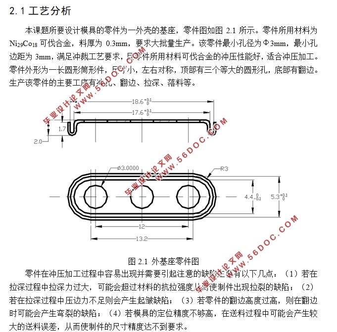
工艺分析
本课题所要设计模具的零件为一外壳的基座,零件图如图2.1所示。零件所用材料为Ni29Co18可伐合金,料厚为0.3mm,要求大批量生产。该零件最小孔径为Φ3mm,最小孔边距为3mm,满足冲裁工艺要求,且零件所用材料可伐合金的冲压性能好,适合冲压加工。零件外形为一长圆形筒形件,尺寸小,左右对称,顶部有三个等大的圆形孔,底部有翻边。生产该零件的主要工序有冲孔、翻边、拉深、落料等。
目 录
第1章 绪论 1
1.1 冲压技术的现状及发展趋势 1
1.2 本次设计的主要内容 2
第2章 工艺分析及排样设计 4
2.1工艺分析 4
2.2 排样设计 5
2.3 材料利用率的计算 5
2.4 毛坯尺寸计算 6
2.4.1翻边工位毛坯尺寸的计算 6
2.4.2 拉深工位毛坯尺寸的计算 7
2.5 冲压力的计算 7
2.5.1 拉深力的计算 7
2.5.2 冲裁力的计算 7
2.5.3 翻边力的计算 8
2.6 确定步距和条料宽度 8
2.7 压力中心的计算 8
2.8 初选压力机 8
第3章 模具设计及拉深工位的模拟与分析 10
3.1 凸凹模刃口尺寸计算 10
3.1.1 冲孔凸凹模刃口尺寸计算 10
3.1.2 落料凸凹模刃口尺寸计算 10
3.1.3拉深模工作部分设计 10
3.1.4翻边模工作部分设计 11
3.2 级进模主要零部件设计 11
3.2.1 凸凹模 11
3.2.2 落料翻边复合模 12
3.2.3 模架与模柄 12
3.2.4 导料装置与卸料装置 12
3.2.5 其他零件 13
3.3 压力机校核 13
3.4 模具工作过程分析 13
3.5 拉深工位的模拟分析 14
第4章 模具成本估算 18
4.1 进行模具成本估算的原因 18
4.2 级进模成本估算的特点 18
4.3 模具总成本估算 18
第5章 小结 20
参考文献 22
|