踏板组件冲压模具设计(含CAXA零件图装配图)(选题审题表,任务书,开题报告,外文翻译,论文说明书5500字,CAXA图10张)
摘 要
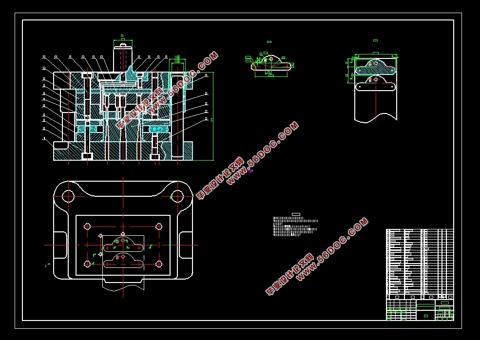
此设计说明书的内容里,包含有两个方面的内容,其一是有关模具的主要发展形势,其二是我对于踏板组件的冲压模具设计介绍。我主要负责设计的是该U型件的冲孔、落料工序,用复合模完成该部分工序的生产。首先考虑了产品的质量要求和生产的实际情况,确定了最佳工艺方案,同时计算下料展开尺寸和零件压力中心,计算模具中的凸凹模刃口尺寸,校核凸模强度以及压力机的核查,精确详细地对有关工艺参数进行计算,准确无误的选择压力设备,同时对模具零件的结构进行设计,适应了目前冲压模具的设计要求。然后进行冲压模具设计,全部采用AutoCAD软件进行图样设计,绘制出了二维装配图和零件图,设计相关零部件结构,最后介绍了装配工艺要求。
关键词:模具制造;复合模;装配;AutoCAD
Abstract
The content of this design specification includes two aspects, one is the main development situation of the mold, and the other is my introduction to the stamping mold design of the pedal assembly. I am mainly responsible for the design of the punching and blanking process of the U-shaped part, and use the compound die to complete the production of this part of the process. First of all, considering the quality requirements of the product and the actual situation of production, the optimal process plan is determined. At the same time, the blanking development size and the pressure center of the parts are calculated, the cutting edge size of the convex and concave die in the die is calculated, the punch strength and the verification of the press are checked, the relevant process parameters are calculated accurately and in detail, the pressure equipment is selected accurately, and the knot of the die parts is determined The structure is designed to meet the design requirements of the current stamping die. Then the stamping die design, all using AutoCAD software for drawing design, drawing out two-dimensional assembly drawings and parts drawings, design the structure of related parts, and finally introduce the assembly process requirements.
Keywords: mold manufacturing; compound mold; assembly; AutoCAD
.2工艺性分析
选取零件材料铝镇静钢板(08AL),其抗剪强度σb=325 MPa,可塑性好、韧性也好,满足该产品的性能及工作条件。同时该零件的形状结构简单,没有尺寸精度及表面粗糙度要求,便于模具设计加工和装配,方便制定工艺规程。
确定冲压件生产的总体工艺方案
3.1确定冲压工序方案
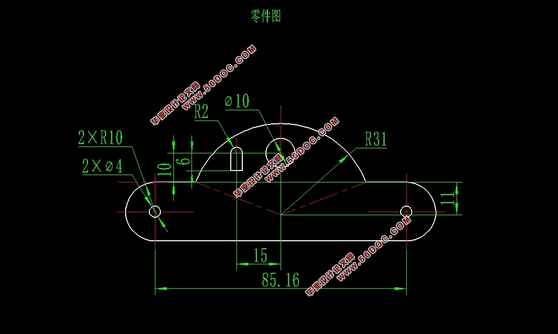
这个踏板组件零件可以直接从零件图上看出有冲孔、落料、弯曲、切舌等工序,本篇中我主要负责设计它的冲孔、落料两道工序,选用单工位复合模,即冲孔落料复合冲压。


目 录
第一章 绪论 1
1.1模具市场发展趋势 1
1.2模具设计技术的发展 1
第二章 零件的工艺性分析 1
2.1零件图 1
2.2工艺性分析 2
第三章 确定冲压件生产的总体工艺方案 2
3.1确定冲压工序方案 2
3.2排样设计 2
第四章 计算冲裁力及确定压力中心 4
4.1计算冲裁力 4
4.1.1冲孔冲裁力的计算 4
4.1.2落料冲裁力的计算 4
4.1.3卸料力和推件力的计算 4
4.2冲压设备的选择 4
4.3确定压力中心 5
第五章 模具总体结构设计 6
5.1.凸、凹模间隙值的确定 6
5.2.凸、凹模刃口尺寸的确定 7
5.3主要零部件的设计 8
5.3.1冲孔凸模 8
5.3.2冲孔落料凸凹模 11
5.3.3落料凹模 12
5.3.4凸模固定板 13
5.3.5凸凹模固定板 14
5.3.6模架选用 14
5.3.7模柄 15
5.3.8卸料装置 15
5.4模具总装图 16
第六章 压力机的校核 17
6.1公称压力的校核 17
6.2装模高度的校核 17
第七章 模具装配要求 18
7.1保证设计参数 18
7.2正确装配组件与零件 18
参考文献 19
致谢 20
|


