汽车进气歧管下壳模具结构设计及其成型过程CAE分析(含CAD图,SolidWorks三维图)(任务书,开题报告,论文说明书16700字,CAD图6张,SolidWorks三维图,答辩PPT)
摘要
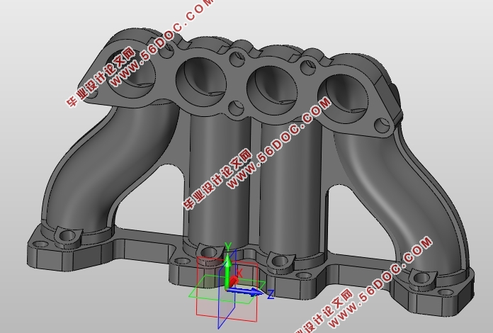
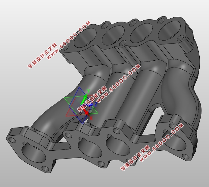
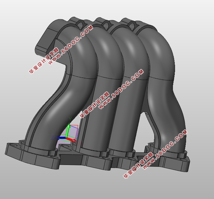
本文首先根据产品使用要求进行进气歧管下壳的结构设计,然后针对塑件结构进行成型工艺性分析并确定注塑模具初步设计方案。参考材料技术数据,确定初始成型条件,借助Moldflow对进气歧管下壳进行成型过程仿真分析,以控制变量法的思路对成型方案进行优化。根据塑件结构特点及仿真结果设计合适的开合模注塑模具,并建立三维模型。通过借助Moldflow软件,模拟仿真成型过程,及时发现成型问题并对塑件结构、成型条件及模具结构进行改进,有效缩短注塑模具设计的周期。对进行其他型号进气歧管注塑模具设计及成型过程优化具有指导意义。
论文主要探讨了浇口位置、充填时间、熔体温度、保压时间等成型工艺参数对进气歧管下壳注塑过程的影响规律。研究表明:在材料Zytel 70G30 HSLR推荐的成型工艺参数范围内,进气歧管下壳的最大变形量随熔体温度的增加而增大,随注射时间的增加而增大,随保压时间的增加而减小。
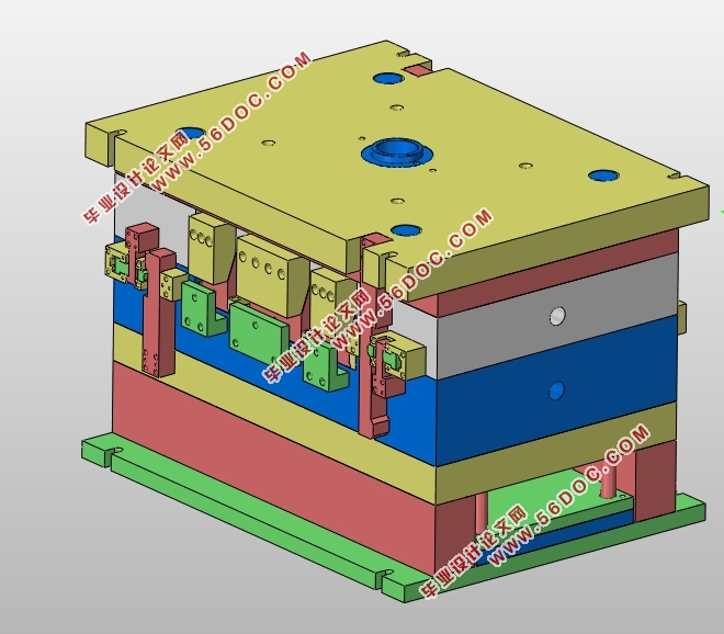
针对塑件结构特点设计注塑模具结构总体方案,包含型腔、浇注系统、导向机构、推出机构、分型抽芯机构、定距机构及冷却系统,进行理论计算及校核,并建立注塑模具三维模型。
本文的特色:运用控制变量法对成型方案逐步进行优化,改善进气歧管下壳熔接痕、翘曲等缺陷。针对进气歧管下壳侧向通孔及内侧通孔等复杂结构特征进行分型抽芯结构设计以解决进气歧管下壳脱模问题。
关键词:塑料进气歧管下壳;注塑成型仿真分析;注塑模具结构设计;斜导柱侧向抽芯机构;弯销内侧抽芯机构
Abstract
This paper designs the structure of plastic air intake manifold according to the requirements of product use,and then analysis to forming technology and design injection mold preliminary scheme.Reference material technical data to determine initial condition.Analyze the molding process of the plastic part by Moldflow and optimize molding process by control variable method.Design injection mould and build the 3D model according to the structure characteristic and simulation result.It is effective to shorten the design period of injection mold by finding the molding problem and improving the process ofinjection molding simulation analysis.It is of great significance to optimize the design of injection mould and molding process for other types of plastic air intake manifold.
The paper mainly discusses the influence of gate position, filling time, melt temperature and holdup time on the injection molding process.Studies show that the material Zytel 70G30 HSLR recommended range of molding process parameters, the maximum deformation of the intake manifoldincrease with the increase of melt temperature and the injection time and decreases with the increase of the time of protection
According to the characteristics of the plastic parts structure design of injection mold structure overall scheme, including cavity, Gating system, guide mechanism, demoulding mechanism, core pulling mechanism, distance institutions and cooling system. Carry out theoretical calculation and check, and set up the 3d model of injection mold.
The characteristics of this paper:Using the control variable method to optimize the molding scheme, improve the defects of weld lines and warpage. Through analyzing the characteristics of plastic parts, design core pulling mechanism to solve the problem mold release.
Key Words:the drag shell of plastic air intake manifold;injection molding simulation analysis;Design of injection mold structure;side core-pulling mechanism;inner side core-drawing mechanism
目录
第1章 绪论 1
1.1 研究的目的和意义 1
1.2 国内外研究现状 1
1.3 研究的基本内容 2
1.4 研究的技术路线 2
第2章 进气歧管下壳结构设计 4
2.1 进气歧管下壳设计要求 4
2.2 进气歧管下壳结构设计 4
2.3 进气歧管下壳成型工艺性分析 4
2.3.1 进气歧管下壳成型工艺 4
2.3.2 进气歧管下壳材料选用 5
2.4 本章小结 6
第3章 注塑成型仿真分析 7
3.1 软件介绍 7
3.2 模型前处理 7
3.3 浇口位置及浇口数量分析 7
3.3.1 充填时间 9
3.3.2 翘曲变形 10
3.3.3 熔接线 11
3.3.4 气穴 12
3.4 翘曲原因 13
3.5 工艺参数优化 14
3.5.1 熔体温度 14
3.5.2 注射时间 17
3.5.3 保压时间 19
3.6 冷却方案改进 21
3.7 总体优化方案对比 22
3.8 本章小结 22
第4章 注塑模具结构设计 24
4.1 注塑机型号的选定 24
4.1.1 注塑量计算 24
4.1.2 浇注系统凝料体积初步计算 24
4.1.3 注塑机型号选择 24
4.1.4 注塑机技术参数校核 24
4.2 模具结构总体方案设计 25
4.2.1 浇注系统 25
4.2.2 分型抽芯机构 25
4.2.3 推出机构 26
4.3 分型面的确定 26
4.3.1 型腔分型面 26
4.3.2 分型顺序 26
4.4 成型尺寸及内模镶件尺寸计算 27
4.4.1 成型尺寸计算 27
4.4.2 内模镶件尺寸计算 29
4.5 分型抽芯结构设计及计算 29
4.5.1 斜导柱侧向抽芯机构 29
4.5.2 弯销内侧抽芯机构 31
4.6 浇注系统设计及计算 31
4.6.1 主流道设计及计算 31
4.6.2 分流道设计及计算 32
4.6.3 剪切速率校核 32
4.7 推出机构设计及计算 32
4.7.1 脱模力计算 32
4.7.2 推杆直径校核 33
4.7.3 推杆位置布置 33
4.8 定距机构设计与计算 33
4.8.1 模具拉杆长度计算 33
4.8.2 双扣机定距机构 34
4.9 冷却系统的设计与计算 34
4.9.1 冷却系统设计 34
4.9.2 冷却系统的理论计算 35
4.10 排气系统设计 36
4.11 模架的确定及校核 36
4.11.1 模架的确定 36
4.11.2 模架尺寸校核 37
4.12 进气歧管下壳注塑模具详细结构 37
4.13 本章小结 38
第5章 结论 39
参考文献 40
附录 42
致谢 48
|
