变压器储油柜端盖复合模设计(含cad零件图和装配图)
来源:56doc.com 资料编号:5D9806 资料等级:★★★★★ %E8%B5%84%E6%96%99%E7%BC%96%E5%8F%B7%EF%BC%9A5D9806
资料以网页介绍的为准,下载后不会有水印.资料仅供学习参考之用. 密 保 惠 帮助
资料介绍
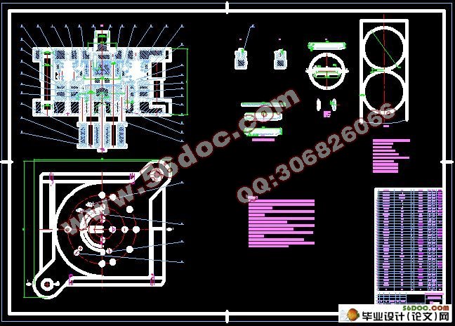
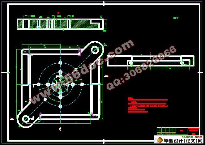
变压器储油柜端盖复合模设计(含cad零件图和装配图)(选题审批表,任务书,开题报告,中期检查表,说明书13900字,CAD图纸12张)
摘 要:由于此次设计的变压器储油柜端盖中间有凸起结构,故在拉深过程中,需采用镶拼式凸模,使工件扯裂整形。模具采用顺装结构,即用顶杆装置从下往上使工件顶出;通过分析变压器储油柜端盖的结构和成形工艺,计算毛坯尺寸、冲压力及刃口尺寸,设计出了一套集落料、拉深、冲孔三工序为一体的复合模的模具结构。在整个设计过程中,重点设计其工艺结构零件和辅助结构零件,最后对模具的强度进行检验以论证其可能性,从而保证了制品的质量,提高端盖的生产效率。
关键词:端盖复合模;落料;拉深;冲孔
Design of Composite Mould For Transformer Oil Storage Cabinets Cover
Abstract: In this design,there is a raised structure in the middle of the transformer oil storage cabinets cover. So it is needed a mosaic-style punch to make the workpiece possible to rip plastic and reshaped in the drawing process. The mould is in a smooth structure.In other words,taking the pin-lift arrangement to push out the workpiece from the bottom up to the top.Through the analysis of the structure of the transformer oil storage cabinets and the craftwork of figuration,and through the calculation the rough size,pressure and the cutting edge size A compound die structure combined with blanking,drawing,punching the three processes as an arganic whole was carried out..In this whole design process, the mould’s structural components and supporting structure is the roughcast priority excogitation.At last,by checking the strength of the mould in order to prove its possibility to contribute the products high quality and develop the cover productivity.
Key words: the composite mould for the cover;blanking; deep drawing; punching
工件图纸分析
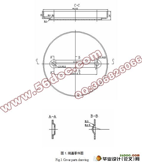
变压器储油柜端盖的材料为未经退火的Q235钣金零件,,材料厚度为t=2mm,
生产批量较大,零件简图如下页图中所示;
由图1知,该零件结构较为复杂,是由圆弧和直线组成,对称,图上尺寸在1~180㎜,据教材《冷冲压模具设计与制造(第2版)》第7页,表2.3,可知该冲裁件内外形所能达到的经济精度为IT11—IT14;其中零件图上孔边距孔心距为120±0.5,即120mm的公差为±0.5;属IT12级精度,零件图上所有未标注公差的尺寸,属于自由尺寸
目 录
摘 要 1
关键词 1
1 前言 2
2 工件工艺性分析 2
2.1 工件图纸分析 2
2.2 工序顺序的确定 3
3 制定工艺方案 4
3.1 工艺方案的分析 4
3.1.1修边余量的计算 4
3.1.2毛坯尺寸的计算 4
3.1.3确定拉深系数 8
3.1.4确定是否使用压边圈 9
3.2 工艺方案的确定 9
4工艺计算 9
4.1 材料排样及材料利用率的计算 9
4.2 确定板料规格和裁料方式 10
4.3 压力中心的计算 10
4.4 刃口尺寸与公差的计算 11
4.4.1落料 11
4.4.2拉深 12
4.4.3冲孔 12
4.5 冲压力的计算及冲压设备的初选 13
4.5.1落料 13
4.5.2拉深 14
4.5.3冲孔 15
5 模具总体分析 16
5.1 模具工作过程的分析 16
6 模具主要零部件的结构设计 16
6.1 模具工作部分零件 16
6.1.1落料凸模 16
6.1.2落料凹模 17
6.1.3拉深凸模 17
6.1.4拉深凹模 17
6.1.5冲孔凸模 18
6.1.6冲孔凹模 18
6.2 安装紧固零件的设计 18
6.2.1模柄的设计 18
6.2.2模架的设计 18
6.2.3上、下模座的设计 18
6.2.4固定板的设计 19
6.2.5垫板的设计 19
6.2.6螺钉的设计 19
6.2.7销钉的设计 20
6.3 导向零件的设计 20
6.3.1导柱 20
6.3.2导套 20
6.4 卸料和顶件装置的设计 21
6.4.1卸料装置的设计 21
6.4.2顶件装置的设计 22
7 模具强度校核 23
7.1 冲孔凸模的强度校核 23
7.2 螺钉的强度校核 23
8 冲压设备的选定 24
8.1 压力机类型的选择 24
8.2 压力机规格的确定 24
9 结论 25
参考文献 25
致 谢 26
附 录 26
|


