数控车床上下工件机械手设计(任务书,开题报告,外文翻译,进度计划表,论文说明书17000字,cad图纸5张)
摘 要
本设计是数控车床上下工件机械手的设计,包括总体方案的确定,机械结构的设计以及重要部件的设计。随着现代工业的发展和竞争的加剧,对加工效率提出了新的要求,数控车床工件装卸自动化就成为当前制造厂家对机床的重要需求之一。为了满足用户的需求,当前中国的机床制造厂开始在部分数控车床上配置工件自动上下料机械手。但如果采用伺服电机驱动和控制其成本高、结构复杂、速度慢、工作效率较低;如果采用液压驱动,其泄漏对数控要求的清洁环境造成一定的副面影响。随着气动技术的不断发展,气体驱动也能成为机械手的驱动力量,其成本底,结构简单,工作效率高,清洁,再加上PLC控制系统实现机电气一体化控制。
本设计主要设计用低成本、高速的气缸来组成模块化的气动机械手,实现数控车床工件自动装卸,克服伺服电机应用中存在的高成本和低效率的局限。论文完成的主要设计工作包括以下几个方面:(1)设计了模块化气动装卸机械手的总体结构;(2)研究了大跨度气缸的固定支撑形式;(3)研究了水平运动气缸的防侧翻技术;(4)研究并实现了气缸输出杆高精度柔性调节技术(5)初步设计了气动控制回路和PLC控制系统。
关键词:机械手;自动化;上下料;气体驱动
Abstract
This design is the numerical control lathe workpiece manipulator design, including the determination of overall scheme, design of mechanical structure design and important parts. Along with the development of modern industry and the competition put forward new requirements to processing efficiency, numerical control lathe workpiece loading and unloading automation becomes the current manufacturer's one of the important requirements for machine tools. In order to meet the needs of users, the current China's machine tool manufacturers began on the part of numerical control lathe automatic up-down material manipulator configuration artifacts.But, if the servo motor drive and control its high cost, complex structure, slow speed, the efficiency is low; If adopts hydraulic drive, the leak on the CNC requirements of clean environment certain side effects.With the continuous development of pneumatic technology, gas drive also can become a driving force of the manipulator, end of the cost, simple structure, high efficiency, clean, coupled with the PLC control system to realize integration of mechanical and electrical gas control.
This design is mainly design with low cost, high speed of the cylinder to form a modular pneumatic manipulator, and implement numerical control lathe automatic loading and unloading of workpiece, overcome existing in the application of servo motor limitations of high cost and low efficiency. The thesis completed the main design work includes the following several aspects: (1) the overall structure of the design of modular pneumatic loading and unloading manipulator; (2) study the long-span cylinder fixed support form; (3) studies the technique of side flip horizontal motion cylinder; (4) the research output and implements the cylinder rod (5) high precision flexible adjustment technology pneumatic control loop and PLC control system is designed.
Key words:manipulator;automation;up-down material ;gas drive
机械手的技术参数
工业机械手的技术参数是说明机械手规格和性能的具体指标,一般包括以下几个方面:
(1)抓重(又称臂力):额定抓取重量或称额定负荷,单位为公斤;
(2)自由度数目和坐标形式:整机,手臂和手腕等运动共有几个自由度,并说明坐标形式;
(3)定位方式:固定机械挡块,可调机械挡块,行程开关,电位器及其他各种位置设定和检测装置;
(4)驱动方式:气动,液动,电动和机械式四种形式;
(5)手臂运动参数;
(6)手腕运动参数;
(7)手指夹持范围和握力;
(8)定位精度:位置设定精度和重复定位精度;
(9)轮廓尺寸:长×宽×高(毫米);
(10)重量:整机重量。
本设计的主要参数
(1)用途:数控机床自动上下工件
(2)设计技术参数:
1) 抓重:600g (夹持式手部)
2) 自由度数:4个自由度
3) 坐标型式:直角坐标型
4) 横臂手臂长度:2180mm
5) 手臂最大高度:2769.5mm
6) 手臂运动参数
升降行程:920mm
升降速度:167mm/s
7) 手腕运动参数
回转范围: 0-180°
3 各模块的设计
3.1 机械手手部模块的设计
3.1.1 手部设计基本要求
(1) 应当具备适当的加紧力和驱动力。应当考虑到在一定的加紧力下,不同的传动机构所需的加紧力不同。
(2) 手指应具有一定的张开范围,手指应该具有足够的开闭角度(手指从张开到闭合绕支点所转过的角度)Δγ,以便于抓取工件。
(3) 要求结构紧凑、重量轻、效率高,在保证本身刚度、强度的前提下,尽可能使结构紧凑、重量轻,以利于减轻手臂的负载。
(4) 要便于安装和维修,易于实现计算机控制。用计算机控制最方便的是电气式执行机构。因此,机械手手部设计的主流是电气式,其次是液压式和气压式(在驱动接口中需要增加电-液或电-气变换环节)。
(5) 应保证手抓的夹持精度。[4]
目录
摘 要 IV
Abstract V
目 录....... VI
1 绪论 1
1.1 前言和意义 1
1.2 工业机械手的简史 1
1.3 国内外研究现象和趋势 2
1.4 设计原则 3
2 数控车床上下工件机械手的总体设计 4
2.1 技术要求 4
2.2 机械手总体设计 4
2.2.1 执行机构的选择 4
2.2.2 驱动机构的选择 5
2.2.3 传动结构的选择 5
2.2.4 机械手的基本形式选择 7
2.2.5 机械手直臂部分的主要部件及运动 8
2.2.6 机械手的技术参数 8
3 各模块的设计 10
3.1 机械手手部模块的设计 10
3.1.1 手部设计基本要求 10
3.1.2 典型的手部结构 10
3.1.3 机械手手爪的设计计算 10
3.2 机械手腕部模块的设计 14
3.2.1 腕部设计的基本要求 14
3.2.2 腕部的结构以及选择 14
3.2.3 腕部的设计计算 15
3.3 机械手手臂模块的设计 16
3.3.1 手臂的结构的选择及其驱动机构 16
3.3.2 滚珠丝杠设计 16
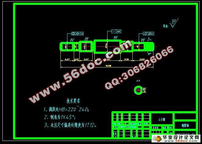
3.3.3 锥齿轮及锥齿轮轴的设计 18
3.3.5 电机选型 21
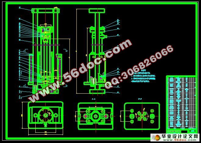
4 直臂导杆气缸的设计 22
4.1 气缸体的设计 22
4.1.1 预选气缸的缸径 22
4.1.2 预选气缸的行程 22
4.1.3 气缸的类型选择 23
4.1.4 活塞杆直径d的计算 23
4.1.5 气缸筒壁厚 的计算 23
4.1.6 气缸输出拉力的校核 24
4.1.7 耗气量的计算 24
4.2导杆机构的设计 25
6 结论与展望 27
致谢 28
参考文献 29
|