配合件的数控加工工艺分析与仿真(任务书,外文翻译,论文说明书13000字,CAD图纸2张,答辩PPT)
摘 要
数控技术,是采用数字控制的方法对某一工作过程实现自动控制的技术。它所控制的通常是位置、角度、速度等机械量和与机械能量流向有关的开关量。数控的产生依赖于数据载体和二进制形式数据运算的出现。而数控铣床是在普通铣床上集成了数字控制系统,可以在程序代码的控制下较精确地进行铣削加工的机床。
本文为配合零件的编程与加工,通过数控铣床的加工,针对具体的零件,进行了工艺方案的分析,加工方案的确定,刀具和切削用量的选择,确定加工顺序和加工路线,数控加工程序编制。本文主要从三维模型的建造、加工工艺分析和机床编程的一般步骤着手,提高我对CAD/CAM软件的使用与认识、提高我的读图绘图能力。最后通过自动编程与加工,希望能在过程中发现更好的编程方法和加工方法,提高效率,而且运用于实际工作中能够更深入的了解数控机床的加工特点。
关键词:数控铣床,配合零件,三维模型,加工工艺,自动编程
ABSTRACT
Numerical control technology, is the method that USES digital control of one of the working process of automatic control technology. It is usually controlled by the position, Angle, speed and other mechanical quantity and amount related to the mechanical energy flow switch. Numerical control depends on the data carrier and the binary form data operation. And CNC milling machine is in the common milling machine used digital control system, can be under the control of the program code accurately for milling machine.
This article for programming and machining of the parts, through the processing of CNC milling machine, for specific parts of the process of analysis, the scheme of machining tool and cutting parameter selection, determine the processing order and processing route, the nc machining programming. This article mainly from the construction of the 3 d model, processing technology analysis and the general steps of machine tool programming, improve my understanding of the use of CAD/CAM software and figure drawing, improve my reading ability. Finally, automatic programming and processing, the hope can find better ways of programming and processing in the process method, improve efficiency, and applied to real work can further understand the machining characteristic of nc machine tools.
KEY WORDS: CNC milling machine, cooperate with parts, 3 d model, processing technology, automatic programming
零件毛坯选择
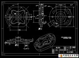
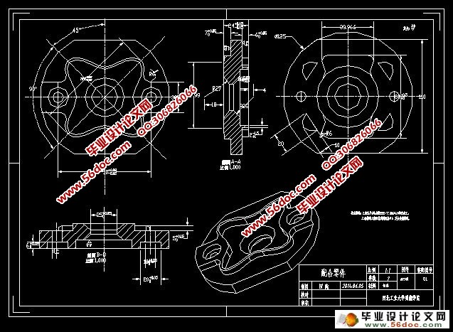
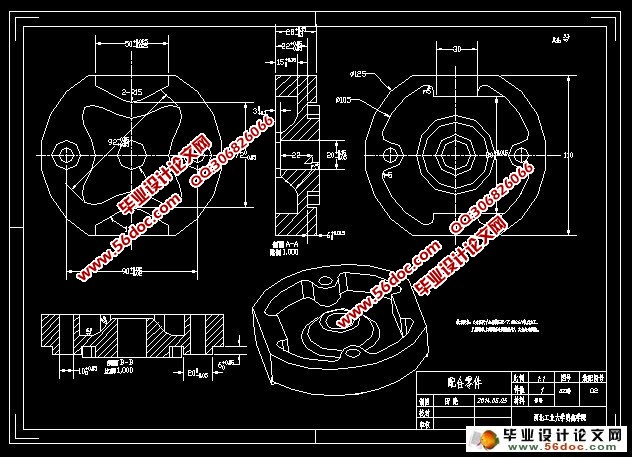
两配合件01、02从图上可以看出大轮廓为Φ125mm大圆,切掉两端两平端距离为110mm。01工件厚24,02工件厚30。考虑到现有机床工作台面是一个平面所以装夹方式是用压板压,所以先下料219*114*26mm和219*114*34mm各留2mm余量。下料长219mm是留有两端压压板45mm余量。
材料:铝料。
目 录
第一章 绪 论 5
1.1数控技术发展及现状 5
1.1.1数控技术的发展 5
1.1.2数控技术在国内的现状 5
1.2本课题研究的目的及意义 6
1.3课题的主要内容 7
第二章 零件的工艺分析 8
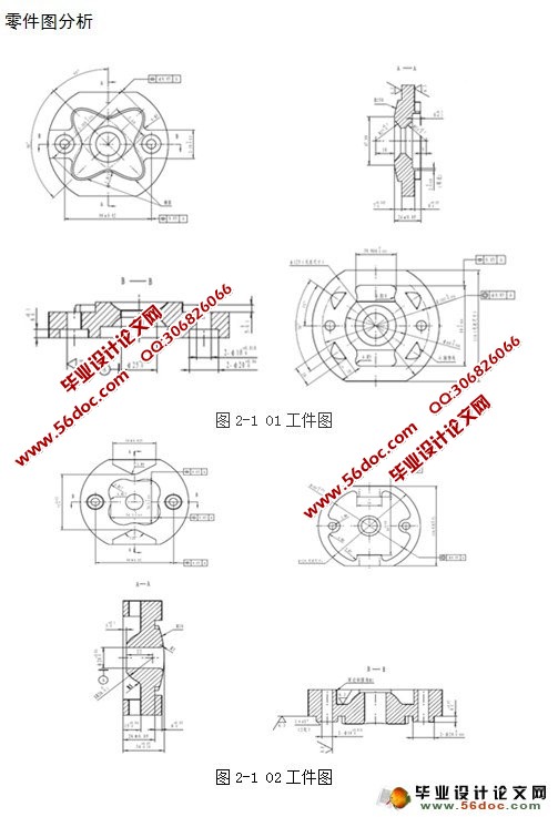
2.1零件图工艺分析 8
2.1.1零件图分析 8
2.1.2零件毛坯选择 9
2.2零件定位基准选择 9
2.2.1精、粗基准选择 9
2.2.2基准的确定 10
2.3 零件加工工艺规程分析 11
2.3.1配合件01工件工艺规程分析 11
2.3.2配合件02工件工艺规程分析 12
第三章 运用pro-E建造三维模型 13
3.1 pro-E简单介绍 13
3.2创建零件模型 14
3.2.1配合件01工件建模 14
3.2.2配合件02工件建模 20
第四章 配合件的编程及加工仿真 24
4.1 UG编程的简单介绍 24
4.2以配合件02工件为例进行UG编程 25
4.2.1对02工件进行模型分析 25
4.2.2加工坐标系、几何体设定 25
4.2.3创建加工刀具 26
4.2.4加工程序顺序管理 26
4.2.5对02工件加工编程 27
4.3刀路仿真及加工代码输出 30
4.3.1刀路仿真及加工代码的输出 30
4.3.2配合件02工件输出部分加工代码 32
第五章 配合件工艺表、程序单 38
5.1配合件01工件工艺表、程序单 38
5.2配合件02工件工艺表、程序单 40
第五章 全文总结 42
致 谢 43
参考文献 44
毕业设计小结 45
附 录 46 |