基于PLC机床的自动控制系统设计(含电路图,程序)(选题表,任务书,论文14200字,CAD电路图,PLC程序,梯形图)
摘 要
三面铣小型机床是进行特殊机床部件加工的专用多功能机床,是机床大家族中重要的一员。我国在机床行业的研发水平和制造技术以及控制技术都远远的落后与发达国家水平,在国际上,把机床的控制精度和设备加工精度看做是衡量一个国家的高端制造水平的标准。采用PLC进行三面铣小型机床的控制系统设计,不但具有较高的可靠性,还能实现机床操作的可视化,系统的集成性好、可靠性高,值得相关技术研究人员的进一步深入研究。
本文在了解了三面铣小型机床的组成结构的基础上,对于PLC控制系统在机床行业及工业控制领域进行了简单了解,并以三面铣小型机床设备为重点,首先分析了机床的工作原理,对机床的工作流程进行深入的分析,剖析了机床的铣削加工工艺。以电气控制系统为主要研究对象,对以继电器控制系统、原始的人工操作系统中存在的若干弊端问题进行分析,设计了以PLC为主要核心,结合外围传感器及液压驱动系统在内的新型控制系统。
文中对控制系统的硬件组成进行了介绍,对接近开关、PLC选型以及液压驱动回路的选型进行了介绍,给出了电气控制系统的原理图,并在硬件设计的基础上,结合控制系统的程序流程图完成了PLC梯形图逻辑控制程序的设计。为了能实现控制系统的可视化监控,本文以组态王组态软件为背景,设计了简单的上位机监控界面,对组态系统的主要建立过程进行简要介绍。
以PLC为控制核心的工业设备过程控制系统,不但具有可靠性高、扩展性强的性能特点,其硬件设备的造价也很低,比较适合于绝大多数工业设备的控制,可以在其他领域进行推广。
关键词: 三面铣小型机床;PLC控制;组态王
Abstract
Three face milling machine tool is a special machine tool components for the processing of special multi-function machine tools, machine tool is an important member of the family. Behind the developed countries and the level of China's machine tool industry in the level of R & D and manufacturing technology and control technology are far, in the world, the machine tool control accuracy and precision equipment as a measure of a country's high-end manufacturing standard. The design of control system adopts PLC three milling machine, not only has high reliability, but also can realize the visualization of machine operation, system integration and high reliability, is worth further research related technology research personnel.
Based on the understanding of the structure of the three milling machine on the PLC control system for a simple understanding of the machine tool industry and the field of industrial control, and three milling machine equipment as the key point, first analyzes the working principle of the machine tool, the workflow of the machine to conduct in-depth analysis, analysis of the milling processing machine.
The hardware of the control system were introduced, the selection of proximity switch, PLC selection and hydraulic drive circuit are introduced, the principle diagram of electric control system is presented, and based on the hardware design, combined with the flow chart of the program control system to complete the design of control program of PLC ladder logic. In order to realize the visual monitoring of the control system, this paper designs a simple monitoring interface of the upper computer based on Kingview configuration software.
With PLC as the core of the process control of industrial equipment control system, not only has the advantages of high reliability, scalability and strong features, the hardware cost is very low, the control is more suitable for the majority of industrial equipment, can be popularized in other areas.
Key words:Three face milling combined machine tool; PLC control ;Kingview
本课题的研究内容
本课题以PLC为主要控制核心,结合三面铣小型机床的工作特点,在了解了机床的切削原理和工作流程的基础上,根据需要进行编码器、光电开关、触摸屏和PLC的选型,最终完成控制系统的硬件设计和软件设计。全论文分五章,各章的主要内容如下:
第一章,对介绍了本课题的来源和研究背景,分别对国内外的研究现状进行简介,对我国各种机床和国外同类产品的差距进行介绍,总结本文的研究意义。
第二章,完成控制系统的整体控制方案设计,系统的组成。
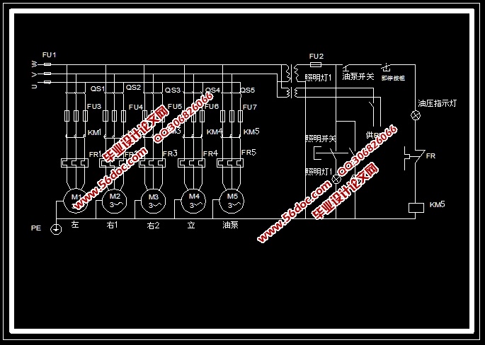
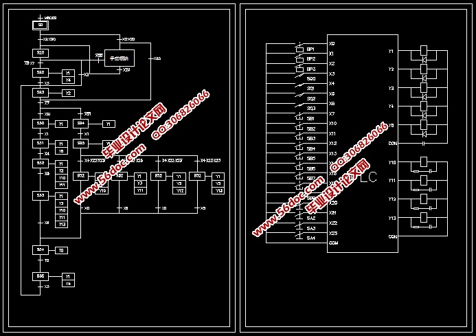
第三章,完成控制系统的硬件方案设计,首先列举PLC的外围电器元件的选型,从电动机、传感器、电机驱动器等多方面综合介绍,明确硬件系统的结构,给出PLC的外围I/O分配结果,并绘制系统的硬件原理图。
第四章,完成控制系统的软件设计,首先介绍PLC的编程环境,绘制小型机床系统的工作流程图,以流程图为基础编制梯形图程序。
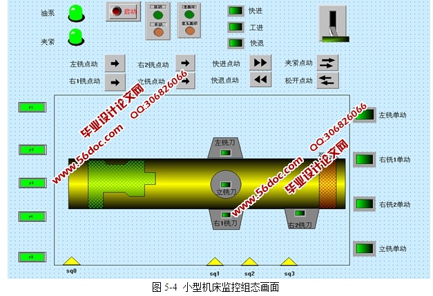
第五章,完成组态画面的设计,通过对组态王软件的学习和介绍,运用组态王6.55组态软件,从工程的建立开始直至画面的设计和通讯组态。
最后,对全文进行总结,并提出今后的研究方向和设计中的不足和心得体会等。
目 录
摘 要 1
Abstract 3
目 录 II
1 绪 论 1
1.1 课题的研究背景和意义 1
1.2 国内外研究现状 3
1.3 本课题的研究内容 4
2 控制方案设计 5
2.1 小型机床对电气控制系统的要求 5
2.1.1 进行铣削加工的工艺流程分析 5
2.1.2 机床的被控对象确定 6
2.1.3 对控制系统的要求 7
2.2 本课题的设计思路 8
2.3 本章小结 9
3 控制系统的硬件设计 10
3.1 设备选型 10
3.1.1 接近开关的选型 10
3.1.2 液压缸动作电磁阀的选型 12
3.1.3 液压系统的设计 13
3.2 PLC系统的I/O信号分配 13
3.3 PLC的选型 14
3.4 硬件原理图的设计 15
3.4.1 驱动电路接线图设计 15
3.4.2 PLC接线图设计 15
3.4.3 操作面板布局设计 16
3.5 本章小结 17
4 控制系统的软件设计 18
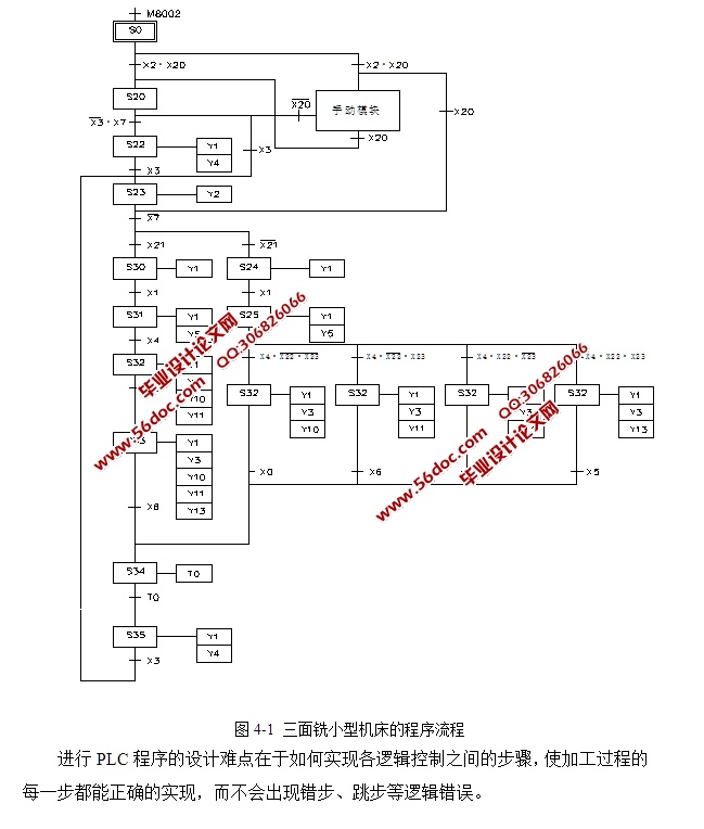
4.1 程序流程图设计 18
4.2 梯形图程序设计环境 19
4.2.1 三菱PLC编程软件简介 19
4.2.2 GX编程软件的使用 19
4.3 PLC程序设计 21
4.3.1 程序的总体结构 21
4.3.2 自动控制程序 22
4.3.3 手动程序 24
4.3.4 其他程序 26
4.4 本章小结 27
5 组态界面设计 28
5.1 组态软件介绍 28
5.2 系统需求分析 28
5.3 组态界面的设计 29
5.3.1 新建组态工程 29
5.3.2 新建画面 29
5.3.3 画面的设计 30
5.4 数据词典中的I/O变量定义 31
5.5 本章小结 32
7 总 结 33
参考文献 35
致 谢 37
附 录 38
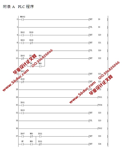
附录A PLC程序 38
|