汽车实验台电路控制系统(附VB,单片机程序,PCB,电路原理图)(任务书,开题报告,中期报告,外文翻译,论文14000字,答辩PPT,实物图,元件清单)
The automobile experiment set electric circuit control system
摘 要
自汽车诞生以来,汽车维修业便一直伴随着汽车工业的发展而成长,汽车维修业已成为交通运输业必不可少的服务性支柱与保障。尤其是近几十年来,随着国家经济水平的发展,高速公路建设发展迅猛,通车里程快速增长。道路状况的改善,使汽车的车速越来越快,与之关系密切的汽车维修业也随着汽车高科技化的发展,出现了一些新的面貌。汽车维修制度的改革和发展及汽车维修技术的变革,促使汽车维修人员培训的教学内容、教学手段、教学设备都应作出相应的改革。因为在现代汽车维修中,有故障的车辆先用检测诊断仪器或设备进行相应的检查,而后由维修技术人员基于自己的知识能力和经验,对检查结果进行综合分析后作出相应的诊断,接下来再由主修人员独立或指导辅修人员完成故障排除或修理任务,查找故障所占的时间达总维修时间的70%以上,因此为了提高汽车维修人员素质和专业技能,以达到提高维修质量和效率的目的,所以开发设计了能进行故障模拟和故障分析诊断的实验台,用于汽车维修从业人员的培训。该实验台带有各种传感器工作时的Flash动画演示,常见故障的维修视频,故障测试等功能教师在利用实验台进行授课时,各种故障现象充分的暴漏使学生更容易理解,记忆也更深刻,学习效率将大幅高。
关键词:VB6.0;Atmega16L;TLC5618 D/A转换芯片;Access数据库
ABSTRACT
From the automobile birth, the car maintenance industry has been accompany with the development but growth of the automobile industry, the car maintenance industry has become the service of the transportation industry essential to have to pay the pillar and guarantee. Particularly,in the last several decades, along with the development of national economic level, the construction and development of expressway is swift and violent, the traffic mileage increases fast. The improvement of the road condition, The improvement of road state make speed of automobile more and more fast, the close relation of car maintenance industry also turns along with the automobile high technology of development, appear some new features.The reform and development of the car maintenance system technical change, the content of course,teaching means,the teaching equipmentseses that urge car maintenance a personnel to train all should make a reform for correspond.Because in the modern car maintenance, the vehicle that has breakdown is using the examination diagnosis instrument or equipments carry on correspond first of check, and then from maintain a technical personnel according to own knowledge ability and experience, makes a diagnosis for correspond towards checking a result after carry on the comprehensive analysis, connect down again from major personnel's independence or guide a minor a personnel completion to break down expel or fix mission, check to seek break down have of time reach 70% of total maintenance time above, so development the design can carry on to break down imitate and break down to analyze diagnosis of experiment set, used for the training of the car maintenance employee, raise the car maintenance personnel's character, thus attain exaltation maintain the purpose of the quality and efficiency.In addition teacher while making use of the experiment set to carry on a teaching, various break down phenomenon well of leak to make suddenly and violently the student comprehend more easily, remember also deeper, study an efficiency will significantly high.
Key Words: VB6.0;Atmega16L;TLC5618;Access- Database
功能介绍
电路分析实验模块
1.传感器执行器检测实验模块
2.电脑控制设置断路、短路模拟及综合故障实验模块
3.嵌入式解码器模块
4.动画演示传感器动作原理模块
5.视频演示故障检测模块
6.具有考核系统和题库模块
目 录
1 引言 1
2 ATMEGA16L单片机 2
2.1单片机的概述 2
2.2单片机的复位电路 3
2.3单片机的晶振电路 5
2.4单片机的程序下载 8
3 数模转换芯片TLC5618 10
3.1 TLC5618功能特性 10
3.2 TLC5618芯片结构 11
3.3 TLC5618的C语言程序 13
4 串口转并口芯片74HC595 14
4.1功能特性 14
4.2芯片结构 14
4.3 时序图 16
4.4 74HC595的C语言程序 17
5 继电器驱动芯片ULN2084 18
5.1功能特性 18
5.2 ULN2084的内部结构图 18
6 单片机串口电路 19
6.1串口通信简介 19
6.2 MAX232电路连接图 19
6.3实物串口连接线示意图 20
7 系统抗干扰设计 21
8 电路分析 22
8.1 驱动电路分析 22
8.2模拟故障分析 22
8.3 PCB板故障代码分布图 23
9 VB软件设计 25
9.1 VB6.0软件介绍 25
9.2功能介绍 26
9.3 VB6.0软件的编程思想 26
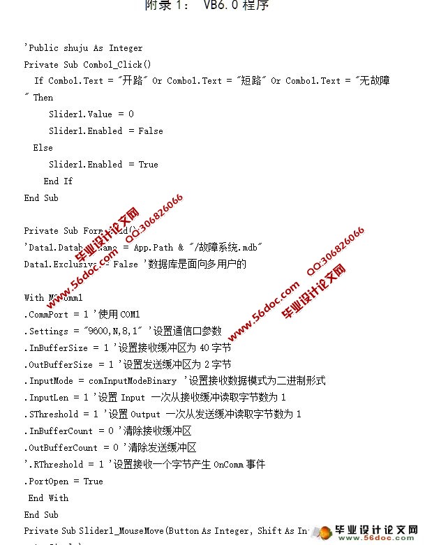
9.4 VB6.0程序(附录1) 27
10 单片机程序设计 28
10.1单片机的编程思想 30
10.2单片机程序流程图 30
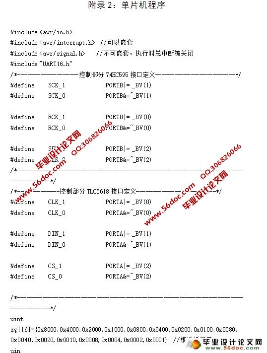
10.3单片机程序(附录2) 30
11 调试结果 31
11.1调试过程 31
11.2 结果 31
结论 32
参 考 文 献 33
附录1:VB6.0程序 34
附录2:单片机程序 37
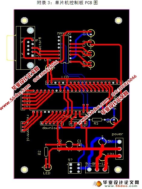
附录3: 单片机控制电路的PCB图 49
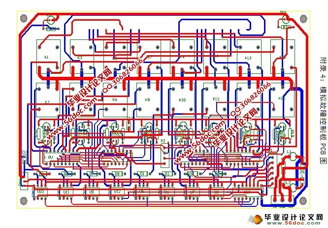
附录4: 模拟故障控制板的PCB图 50
附录5: 开路故障控制板的PCB图 51
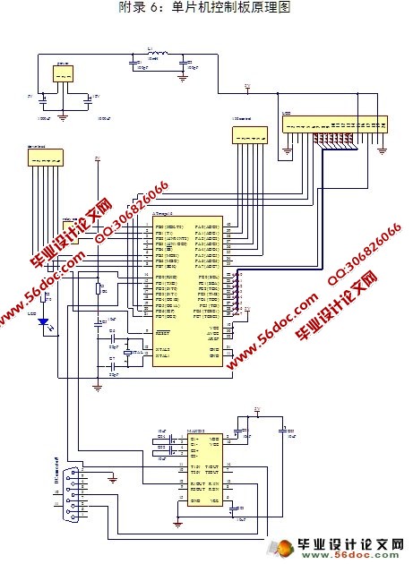
附录6: 单片机控制电路的原理图 52
附录7: 模拟故障控制板原理图 53
附录8: 开路故障控制板原理图 54
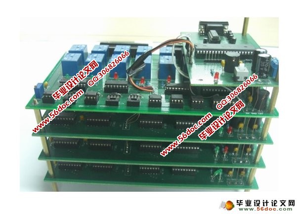
附录9: 整体实物图 55
附录10:英文原文 56
附录11:英文译文 63
致 谢 67
|