远程温度控制系统(无线电发射与接收)(附程序,PCB图,电路原理图)(开题报告,外文翻译,论文24000字)
摘 要
本文论述的远程温度控制是将无线电发射与接收和自动控制相结合的一种控制。基于这种技术,文中将详细介绍“一对多点” 远程温度控制系统的可行性分析,硬件设计,软件设计,以及调试方法等。整个系统包括主、从两个子系统。其中主系统完成对多点设定温度值、设定值显示、实际值显示、失控报警、编码、发射、接收、解码等功能;副系统完成接收、解码、温度采集、温度控制以及编码、发送等功能,这些功能已经全部实现,并且控制温度的超调量最大值仅为2.5%。应用该系统可使操作人员与恶劣的工作环境分离开来,实现生产自动化,提高企业的生产效率。文章的最后还总结了一些设计过程中遇到的问题以及解决方案,供大家参考,同时希望它能够给初级无线电爱好者带来一点点启发。
关键词:显示;编码;发射;接收;解码;传感器。
Abstract
The long-distance temperature controlling this paper presents is a technology of linking wireless receiving and sending to automation. Based on the technology, this paper will introduce the feasibility analysis, hardware designing, software designing and debug methods of one to more points long-distance temperature controlling system in detail. The whole system consists of the main system and subsystem. The main system completes the functions of initializing and displaying the temperature value, displaying actual temperature, alarming when it is out of control, coding and sending, receiving and decoding, and performing one to more points control. The subsystem completes the functions of receiving, decoding, and temperature collecting, controlling, coding and sending. All functions have been realized, and the maximal value of overshoot in process of controlling is 2.5 percent. Applying this system can depart operators from execrable environment, realize producing automation, and improve corporation’s producing efficiency. At last some problems in process of designing and methods for resolving them is described for reference to readers. Meanwhile hope the system can bring a little illumination to wireless lovers.
Keyword: Display; Code; Shoot; Receive; Decoding; Senior
设计任务
1、利用所学的知识设计远程温度控制系统。电烤箱温度可在一定范围内由人工设定,温度信号检测方案自行确定,用单片机采用PID控制算法实现温度实时控制,静态误差1度,超调量〈2.5%,系统温度调节时间ts〈4分钟。控制输出采用脉冲移相触发可控硅来调节加热有效功率。控制温度范围室温--125℃,用十进制数码显示箱内的温度。
2、采用PID控制算法实现温度实时控制,并显示温度实际值。
3、了解计算机控制系统的基本原理和组成;
4、实现无线发送、接收,编码、解码校验。实现超限报警;
5、掌握计算机控制系统的软、硬件设计与调试,实现满足指标要求的控制系统。
主要技术指标:
(1)温度控制误差:≤±0.5℃;
(2)发射频率:≥300MHZ
(3)发射距离:≥500m
(4)误码率:≤10-6
目 录
引言 …………………………………………………………………………………1
1 温度控制的发展及意义 ……………………………………………………1
2 总体设计与可行性分析 ……………………………………………………2
2.1 设计任务…………………………………………………………………………2
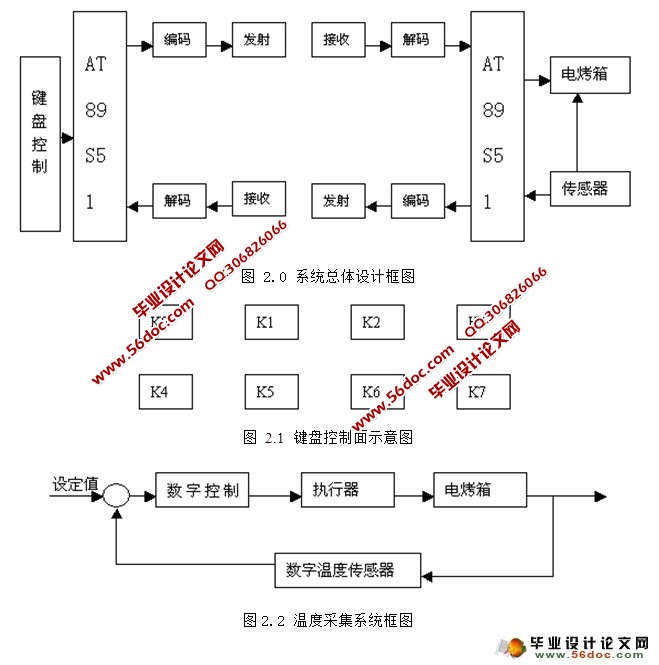
2.2 总体设计框图及概述……………………………………………………………7
2.3 温度采集系统的设计……………………………………………………………2
2.4 数字PID控制设计………………………………………………………………3
2.4.1 PID控制原理 …………………………………………………………………3
2.4.2 数字PID控制算法……………………………………………………………3
2.4.3 改进的数字PID控制算法……………………………………………………4
2.4.4 PID参数整定 …………………………………………………………………6
2.5 可行性分析………………………………………………………………………6
3 硬件设计 ………………………………………………………………………7
3.1 温度采集电路设计………………………………………………………………7
3.1.1 DS18B20内部结构 ……………………………………………………………7
3.1.2 DS18B20的工作时序 …………………………………………………………8
3.1.3 DS18B20与单片机的典型接口设计 …………………………………………9
3.2 单片机控制电路设计 …………………………………………………………12
3.2.1 AT89S51单片机………………………………………………………………12
3.2.2 键盘控制面板 ………………………………………………………………13
3.2.3 LED数码管显示电路…………………………………………………………14
3.2.4在线代码下载电路 …………………………………………………………15
3.2.5驱动电路设计 ………………………………………………………………16
3.2.6报警电路设计 ………………………………………………………………18
3.3 无线收/发电路设计 …………………………………………………………18
3.3.1 编码/解码电路设计 ………………………………………………………18
3.3.2 发射/接收电路设计 ………………………………………………………24
3.4 硬件最后实施方案……………………………………………………………28
4 软件设计 ……………………………………………………………………28
4.1 模块化设计……………………………………………………………………28
4.2 并行键盘显示面板驱动程序设计……………………………………………29
4.3 DS18B20驱动程序设计…………………………………………………………33
4.4 控制电路PWM驱动程序设计…………………………………………………36
4.5 数字PID子程序设计…………………………………………………………37
4.6 程序流程图……………………………………………………………………37
5 系统调试………………………………………………………………………38
5.1 调试步骤………………………………………………………………………39
5.2 模块调试………………………………………………………………………39
5.2.1 控制模块与显示模块调试…………………………………………………39
5.2.2 编码/解码模块调试 ………………………………………………………39
5.2.3 编/解码模块与收/发模块联合调试………………………………………40
5.2.4 驱动电路模块调试…………………………………………………………40
5.2.5 温度采集模块调试…………………………………………………………41
5.3 整体调试………………………………………………………………………41
6 系统性能指标测试…………………………………………………………42
6.1 误码率测试……………………………………………………………………42
6.2 发射/接收频率测试 …………………………………………………………42
6.3 数据传输速率测试……………………………………………………………43
7 操作说明………………………………………………………………………43
8 总结……………………………………………………………………………44
8.1 技术优点与缺点………………………………………………………………44
8.2 提高测量精度的几项措施……………………………………………………44
8.3 问题及解决方法………………………………………………………………44
8.4 整体测试结论…………………………………………………………………45
谢词…………………………………………………………………………………47
参考文献 …………………………………………………………………………48
附录1所需主要仪器设备…………………………………………………………48
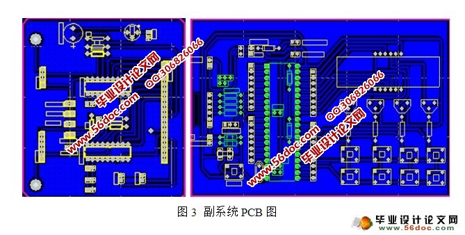
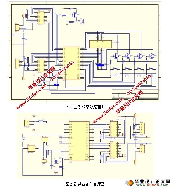
附录2 系统原理图及PCB图………………………………………………………48
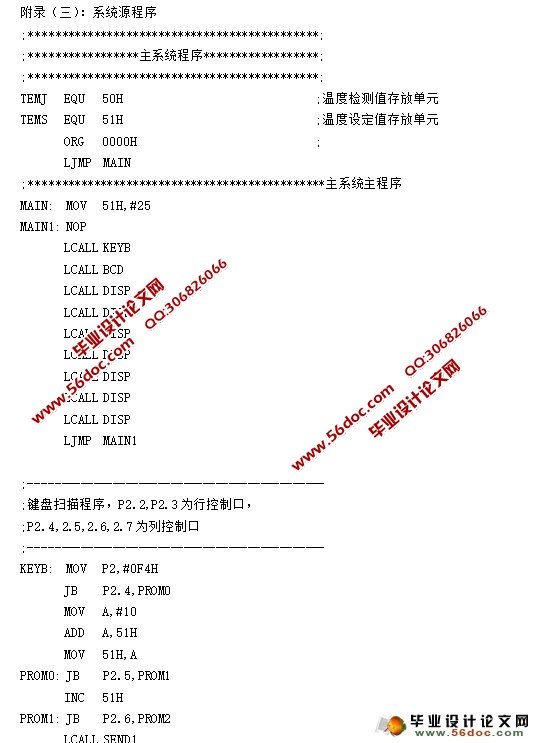
附录3 系统源程序…………………………………………………………………50
|
