低频波形发生器的设计
来源:56doc.com 资料编号:5D26692 资料等级:★★★★★ %E8%B5%84%E6%96%99%E7%BC%96%E5%8F%B7%EF%BC%9A5D26692
资料以网页介绍的为准,下载后不会有水印.资料仅供学习参考之用. 密 保 惠 帮助
资料介绍
低频波形发生器的设计(论文10000字)
摘 要
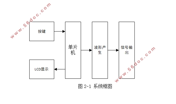
波形发生器作为电子技术领域中最基本的电子仪器,其可产生大量标准信号和用户自定义信号并保证高精度、高稳定性、可重复性和易操作性,故广泛应用于科学研究、工程教育以及生产实践中。本文介绍了一种低频波形发生器的设计与实现。该波形发生器由控制模块、波形产生模块、按键模块和显示模块组成,采用STC89C52单片机作为主控芯片,AD9850作为波形产生装置,LCD1602作为显示装置。本系统经按键电路输入数据,单片机对输入数据进行相关处理在传输给显示模块和波形产生模块进行显示和输出。文中详细介绍了硬件电路的设计原理、软件的设计思路以及软硬件的实验调试过程。经过测试,本系统可输出正弦波、方波,且频率稳定度高,波形良好。
关键词:波形发生器 单片机 频率稳定
Design and implementation of low-frequency waveform generator
ABSTRACT
Waveform generator as electronic technology in the field of basic electronic instrument, which can be produced a large number of standard signal and user-defined signals and to ensure high precision and high stability, repeatability and easy operation, so it is widely used in scientific research, engineering education and practice. This paper introduces the design and implementation of a low frequency waveform generator. The waveform generator consists of control module, waveform generation module, key module and display module, using STC89C52 microcontroller as the main control chip, AD9850 as the waveform generation device, LCD1602 as a display device. This system through the key circuit input data, the input data of the MCU processing in the transmission to display module and waveform generation module for display and output. This paper introduces the design principle of hardware circuit, the design idea of software and the debugging process of software and hardware. After testing, the system can output sine wave, square wave, and the frequency stability is high, the waveform is good.
Key words: Waveform generator;single chip;Frequency stability
目 录
摘 要 I
ABSTRACT II
第一章 绪论 1
1.1 引言 1
1.2 论文主要内容 1
1.3 论文结构安排 1
第二章 低频波形发生器的系统设计 3
2.1 系统总体方案设计 3
2.2 元器件的选择 3
2.2.1 控制模块 3
2.2.2 显示模块 4
2.2.3 波形产生模块 4
2.2.4 按键模块 4
2.3 主要元器件介绍 5
2.3.1 STC89C52芯片 5
2.3.2 AD9850芯片 6
2.3.3 LCD1602芯片 9
第三章 硬件电路的设计 11
3.1 单片机最小系统模块 11
3.1.1 时钟电路 11
3.1.2 复位电路 11
3.1.3 单片机最小系统 12
3.2 按键模块 13
3.3 显示模块 14
3.4 波形产生模块 14
3.4.1 AD9850电路 14
3.4.2 AD9850的控制字和控制时序 15
3.4.3 频率控制字和相位控制字的计算 16
3.4.4 低通滤波器电路 16
3.4.5 外围电路 17
第四章 软件设计 19
4.1 总体设计 19
4.2 按键部分 19
4.3 LCD显示部分 21
4.4 AD9850部分 22
第五章 系统调试 25
5.1 硬件调试 25
5.2 软件调试 29
第六章 总结 31
6.1 论文小结 31
6.2 下一步的工作 31
参考文献 32
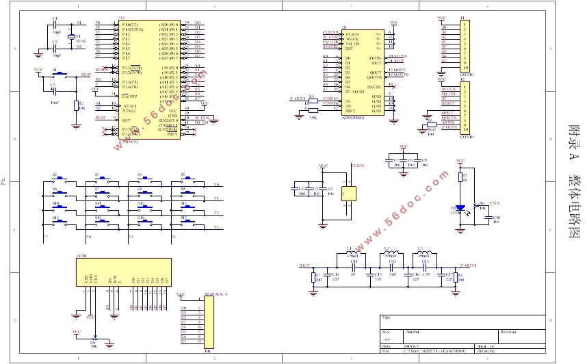
附录A 整体电路图 33
|