脉冲参数测量仪的设计(论文12000字)
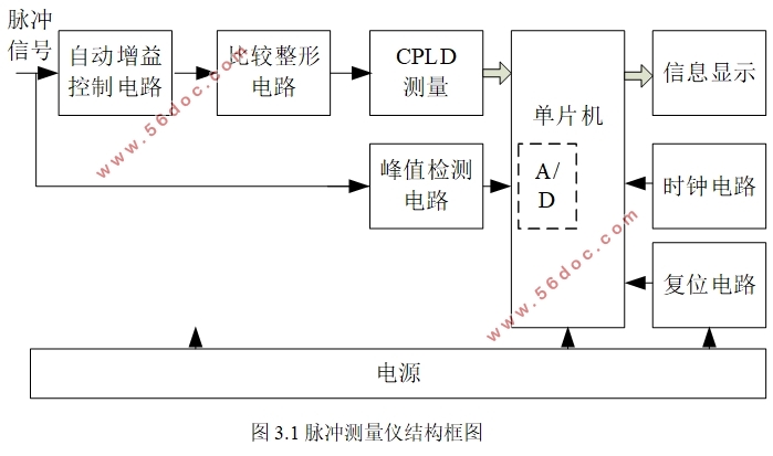
摘要:脉冲信号参数测量仪是用来测量脉冲峰值、频率、占空比等参数的装置。部分脉冲参数测量仪的测量误差受输入信号的影响较大,对信号的幅度和频率范围有较高要求。本文基于等精度测量原理,提出一种以单片机作为主控制器,实现数据处理和人机交互功能,结合CPLD适合处理时序电路的特点,设计高精度脉冲信号参数测量仪。采用自动增益控制(AGC)电路进行信号调理,以适应不同的输入信号,再通过宽带放大、高速比较电路转换成标准脉冲信号,经CPLD的闸门、计数器、通信接口等实体电路进行等精度测量。实验结果表明,频率测量范围在1Hz~2MHz内的相对误差绝对值均不大于10-4,输入信号峰峰值为0.1~5V,测量误差2%,占空比测量范围为 10%~90%,测量误差2%。
关键词:脉冲技术;单片机;CPLD;参数测量
Design of pulse parameter measuring instrument
Abstract:The pulse signal parameter measuring instrument is a device for measuring parameters such as pulse peak, frequency, and duty cycle. The measurement error of some pulse parameter measuring instruments is greatly affected by the input signal, and there is a higher requirement for the amplitude and frequency range of the signal. Based on the principle of equal-precision measurement, this paper proposes a single-chip microcomputer as the main controller to realize data processing and human-computer interaction functions. In combination with the characteristics of CPLD suitable for processing sequential circuits, a high-precision pulse signal parameter measuring instrument is designed. Using automatic gain control (AGC) circuit for signal conditioning, to adapt to different input signals, and then converted to a standard pulse signal through broadband amplification, high-speed comparison circuit, the CPLD gate, counter, communication interface and other physical circuits for other precision measurements. Experimental results show that the absolute value of the relative error in the frequency measurement range from 1Hz to 2MHz is not more than 10-4, the peak value of the input signal is 0.1-5V, the measurement error is 2%, and the duty ratio measurement range is 10%-90%. Measurement error 2%.
Keywords:pulse technology; single chip microcomputer; CPLD; parameter measurement
目 录
1 绪论 1
1.1 脉冲参数测量的意义 1
1.2 国内外研究现状 2
1.3 本文研究内容 3
2 脉冲参数测量仪方案设计 3
2.1 主控制器方案选择 4
2.2 输入信号放大电路 4
2.3 过零比较电路 5
2.4 频率测量方案的选择 5
3 脉冲参数测量仪硬件设计 5
3.1 系统整体方案的设计 5
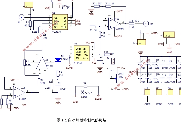
3.2 自动增益控制电路 6
3.3 单片机最小系统 7
3.4 电源模块 8
3.5 按键模块 9
3.6 液晶显示模块 9
3.7 高速比较电路 10
3.8 CPLD电路 10
3.8.1频率测量模块 11
3.8.2上升时间测量模块 12
3.8.3占空比测量模块 12
3.9 峰值测量电路 12
4 脉冲参数测量仪软件设计 13
4.1 CPLD软件设计原理 14
4.2 单片机模块软件实现 14
4.2.1 单片机初始化 14
4.2.2 CPLD数据处理 14
4.2.3 按键处理 15
4.2.4 LCD显示 15
4.2.5 CPLD与单片机的通信程序设计 15
5 脉冲参数测量仪调试 16
5.1 调试方案 16
5.2 测试结果及分析 18
5.2.1 频率测试 18
5.2.2 占空比测试 19
5.2.3 电压幅值测试 19
5.2.4 上升时间测试 19
6 总结 20
参考文献: 20
致谢 22
附录1:实物图 23
|