智能温湿度测量系统的研究与设计(论文11000字,原理图,程序)
摘要:在现代的各种生产生活之中离不开温湿度的控制,在这之中,首要的就是对于温湿度的测量。在电子技术日益进步的今天,各种电子设备都向着操作简便与小型化发展,其中无线通信的发展也起到了重要的作用,温湿度测量设备也不例外。
本毕业设计要求基于单片机来设计一个能够完成温湿度测量的智能系统,用于实时测量温湿度,并且要能够比传统的温湿度计更加方便智能。本设计通过结合使用单片机和温湿度传感器与无线通信模块等设备,实现对测得的温湿度在接收端进行实时数字显示,并且可以设定测量范围,不仅克服了传统的温湿度检测设备的缺点,而且成本低廉,操作难度低,无线传输还使得它具有更广泛的适用性,更加实用。本设计还带有超限报警功能,当温度或者湿度超出预设范围时,接收端指示灯亮起,并且蜂鸣器报警,有效的避免了安全隐患,降低了安全风险。
关键字:温湿度检测、STC89C52、DHT11、nRF24L01、LCD1602
Research and design of intelligent temperature and humidity measuring system
Abstract:In the modern production and life, the control of temperature and humidity is inseparable. Among them, the first is the measurement of temperature and humidity. Today, with the advancement of electronic technology, various electronic devices are moving toward simple operation and miniaturization. Among them, the development of wireless communication has also played an important role, and temperature and humidity measurement equipment is no exception.
The graduation design requires the completion of a research and design of an intelligent temperature and humidity measurement system based on MCS-52. The traditional temperature and humidity detection equipment has the disadvantages of poor measurement accuracy, unintuitive display, and incapable setting of measurement range accurately. The design uses the single-chip STC89C52, temperature and humidity sensor DHT11, nRF24L01 wireless module, liquid crystal display LCD1602 and other equipment to display the measured temperature and humidity in the real-time digital display at the receiving end, and can set the measurement range, overcoming the traditional temperature and humidity detection. The shortcomings of the device have the advantages of wireless transmission, low cost, simple operation and portability. The design also has an over-limit alarm function. When the temperature or humidity exceeds the preset range, the receiving end indicator lights up, and the buzzer alarms, effectively avoiding safety hazards and reducing safety risks.
Key words:Temperature and humidity detection, STC89C52, DHT11, nRF24L01, LCD1602
目 录
摘要………………………………………………………… 4
一、绪论…………………………………………………………… 6
1.1 研究的目的与意义……………………………………………………………… 6
1.2 国内外研究现状………………………………………………………………… 6
1.2.1 国外研究现状…………………………………………………………… 6
1.2.2 国内研究现状…………………………………………………………… 6
1.3研究内容………………………………………………………………………… 7
二、整体设计……………………………………………………… 8
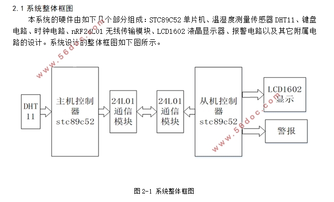
2.1 系统整体框图 …………………………………………………………………… 8
2.2 系统整体原理图………………………………………………………………… 9
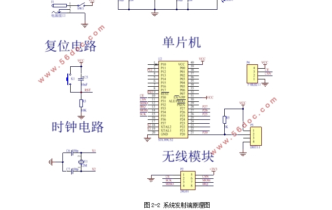
2.2.1 系统发射端的原理图介绍……………………………………………… 9
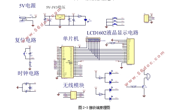
2.2.2 系统接收端的原理图介绍……………………………………………… 9
2.3 整体组成与工作原理 …………………………………………………………… 10
三、系统介绍……………………………………………………… 11
3.1 STC89C52单片机………………………………………………………………… 11
3.1.1 主要特性 ………………………………………………………………… 11
3.1.2 工作模式 ………………………………………………………………… 12
3.1.3 主要引脚功能说明……………………………………………………… 12
3.1.4 复位方式 ………………………………………………………………… 12
3.2液晶显示器介绍 ………………………………………………………………… 13
3.2.1 LCD1602概述 …………………………………………………………… 13
3.2.2 LCD管脚说明……………………………………………………………… 13
3.2.3 LCD1602操作时序………………………………………………………… 13
3.2.4 LCD1602的基本命令 …………………………………………………… 13
3.3 温湿度传感器DHT11 …………………………………………………………… 14
3.3.1 DHT11简单介绍………………………………………………………… 14
3.3.2 DHT11传感器主要功能特性…………………………………………… 15
3.3.3 DHT11传感器的外观与引脚说明……………………………………… 15
3.3.4 传感器性能说明…………………………………………………………… 16
3.3.5 连接接口说明 ………………………………………………………………16
3.3.6 数据格式和编码及处理…………………………………………………… 17
3.3.7 主机复位信号和DHT响应信号 ……………………………………………18
3.3.8 电气相关参数………………………………………………………………20
3.3.9 DHT11的各项注意事项……………………………………………………20
3.4 nRF24L01无线通信模块 ………………………………………………………… 20
3.4.1 nRF24L01的概述 ………………………………………………………… 20
3.4.2 nRF24L01封装图与引脚功能介绍……………………………………… 21
3.4.3 nRF24L01的工作模式 ………………………………………………… 22
3.4.4nRF24L01的配置字 …………………………………………………… 22
3.4.5nRF24L01的跳频应用 ………………………………………………… 22
四、模块电路设计 …………………………………………………24
4.1 最小系统的原理图 …………………………………………………………… 24
4.2 复位电路 ……………………………………………………………………… 25
4.3 时钟电路 ……………………………………………………………………… 25
4.4 下载接口 ……………………………………………………………………… 25
4.5 声光报警电路…………………………………………………………………… 26
4.6 液晶显示电路介绍……………………………………………………………… 27
4.7 nRF24L01无线通信电路原理图 ……………………………………………… 27
五、软件部分设计……………………………………………………28
5.1 系统发射端和接收端的软件流程图…………………………………………… 28
5.2 系统接收端的设定温湿度按键流程图 ……………………………………… 29
六、总结…………………………………………………………… 30
参考文献…………………………………………………………… 31
致谢………………………………………………………………… 32
|
