多点温度无线采集系统的设计(任务书,开题报告,论文15000字)
摘 要
温度是生活中使用最多的参数之一,温度采集被广泛用各个领域。为了保证温度采集的广泛性,往往需要在多个温度测量点进行温度采集,并最终对采集来的温度数据进行汇总分析。然而如果要将各采集点与监测点通过有线连接方式进行连接,将会大大增加系统的复杂性。为了解决上述问题,多点温度无线采集系统应运而生。
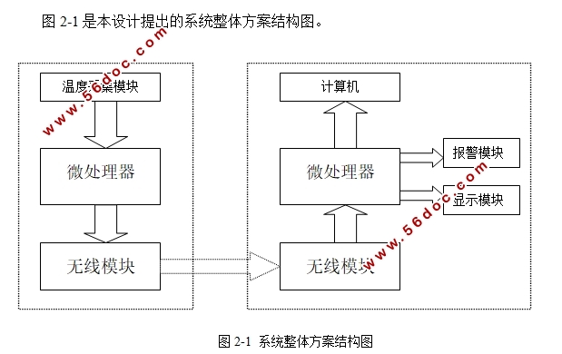
本设计使用NRF24L01无线模块代替了传统复杂的布线手段,同时选用了单片机进行数据处理工作。设计的硬件部分还包括温度传感器模块,LCD显示模块,声音报警模块以及上位机显示模块。为了使系统有效的工作,本文还设计了软件控制部分。
经过测试,本设计的多点温度无线采集系统,能够有效采集目标点的温度数据,并发送至PC机保存,同时可以直观地在LCD显示器上观察到实时温度,而且一旦超出阈值将会进行声音报警。工作预期目标及功能基本实现。
关键词:STC89C52 无线传输 nRF24L01 温度采集
Wireless Multi-point Temperature Acquisition System
Abstract
Temperature is one of the most important parameters , temperature acquisition is widely used in various fields. In order to ensure the universality of the temperature acquisition, temperature acquisition often required in multiple temperature measurement points, and ultimately to the temperature data collection to analysis. However, if the acquisition and monitoring points are connected by a wired connection, will greatly increase the complexity of the system. In order to solve the above problem, emerge as the times require wireless multi-point temperature acquisition system.
This design uses NRF24L01 wireless module to replace the traditional complicated wiring method, by using single chip microcomputer for data processing. The hardware design includes temperature sensor module, LCD display module, sound alarm display module and host computer. In order to make the system work effectively, this paper also designed the software control part.
After testing, wireless multi-point temperature acquisition system design, can effectively collect temperature data of the target, and sent to the PC machine to save, also can be observed in the LCD display real-time temperature, and once exceeded the threshold will sound alarm. The work target and basic function of the realization
Key Words: STC89C52; Wireless transmission; nRF24L01; Temperature acquisition


目 录
摘 要 I
WIRELESS MULTI-POINT TEMPERATURE ACQUISITION SYSTEM II
ABSTRACT II
第一章 绪论 1
1.1 课题研究意义及背景 1
1.2 研究现状及发展趋势 2
1.3 本文所完成的工作及内容安排 2
1.4 论文的组织结构 3
第二章 多点温度无线采集系统整体方案 4
2.1 系统整体方案 4
2.2 系统的硬件结构 4
2.3 系统的软件构思 6
第三章 硬件设计 7
3.1 单片机模块 7
3.1.1单片机选型 7
3.1.2 STC89C52介绍 8
3.1.3 单片机主控制电路 8
3.2系统的发射和接收模块 9
3.2.1无线模块选型 9
3.2.2 NRF24L01无线模块的功能介绍 10
3.2.3 NRF24L01引脚功能及描述 10
3.2.4 实际使用模块实物图及接口电路图 11
3.3 温度传感器模块 12
3.3.1温度传感器选型 12
3.3.2 DS18B20的管脚配置和内部结构 13
3.4 显示模块 13
3.4.1显示模块选型 13
3.4.2液晶显示模块的显示原理 14
3.4.3 LCD1602主要技术参数和引脚功能说明 14
3.4.4 LCD1602接口电路图 15
3.5声音报警模块 16
3.5.1蜂鸣器简介 16
3.5.2蜂鸣器控制部分电路图 16
3.6上位机显示部分 17
3.6.1串口工具的选择 17
3.6.2串口监控器界面 17
第四章 系统软件设计 18
4.1 软件开发环境 18
4.2整体软件流程图 18
4.3 NRF24L01模块程序设计 20
4.3.1 NRF24L01模块初始化 20
4.3.2 NRF24L01模块基本配置 20
4.3.3 NRF24L01模块发送配置 20
4.3.3 NRF24L01模块接收配置 22
4.4温度测量子程序 23
4.4.1 DS18B20初始化 24
4.4.2 DS18B20温度读取 24
4.4.3 DS18B20温度数值设置 25
4.5 LCD1602显示温度子程序 25
4.5.1LCD初始化清屏 26
4.5.2LCD字符显示 26
4.6报警子程序 27
4.7延时程序 27
4.8多点采集的实现 28
4.9上位机显示的实现 28
第五章 系统的调试与结果分析 30
5.1软硬件联调 30
5.1.1硬件调试 30
5.1.2软件调试 31
5.1.3 软硬件联调测试 31
5.2结果分析 32
第六章 总结与展望 34
6.1总结 34
6.2展望 34
参考文献 36
致谢 38
附录一 PCB图 39
附录二 实物图 40
附录三 源程序 41
|


