摘 要
如果采用CPU控制产生PWM信号,一般的PWM信号是通过模拟比较器产生的,比较器的一端按给定的参考电压,另一端接周期性线性增加的锯齿波电压。当锯齿波电压小于参考电压时输出低电平,当锯齿波电压大于参考电压时输出高电平。改变参考电压就可以改变PWM波形中高电平的宽度。若用单片机产生PWM信号波形,需要通过D/A转换器产生锯齿波电压和设置参考电压,通过外接模拟比较器输出PWM波形,因此外围电路比较复杂。
FPGA中的数字PWM控制与一般的模拟PWM控制不同,用FPGA产生PWM波形,只需FPGA内部资源就可以实现。用数字比较器代替模拟比较器,数字比较器的一端接设定值计数器输出,另一端接线性递增计数器输出。当线性计数器的计数值小于设定值时输出低电平,当计数值大于设定值时输出高电平。与模拟控制相比,省去了外接的D/A转换器和模拟比较器,FPGA外部连线很少,电路更加简单,便于控制。脉宽调制式细粉驱动电路的关键是脉宽调制,转速的波动随着PWM脉宽细分数的增大而减小。
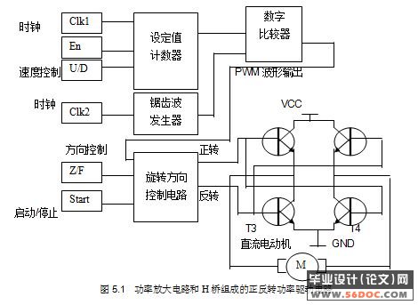
直流电机控制电路主要由三部分组成:
(1) FPGA中PWM脉宽调制信号产生电路。
(2) FPGA中的工作/停止控制和正/反转方向控制电路。
(3) 由功率放大电路和H桥组成的正反转功率驱动电路
关键词:直流电机;控制;脉宽;调制;FPGA;数字比较器
FPGA-based DC motor control PWM
Abstract
If the CPU control of a PWM signal, the general PWM signal through the analog comparator, compared with the end of a given by the reference voltage, and the other termination cyclical linear increase in the sawtooth voltage. When the sawtooth voltage reference voltage output is less than low, when the sawtooth reference voltage greater than high-voltage output. Change the reference voltage can change the PWM waveform in the high-width. If the MCU have PWM signal waveform, through D / A converters have a sawtooth voltage and set reference voltage through an external analog comparator output PWM waveform, the external circuit is rather complicated.
The figures in the FPGA PWM control and the simulation of the general PWM control different, with a FPGA PWM waveform, just FPGA internal resources can be achieved. Compared with figures for comparison instead of analog, digital comparison with the termination of a set of counter output, and the other counter termination linear incremental output. When the linear counter less than the value of exports of low value set, when the set of values than high-value output. Compared with analog control, eliminating the external D / A converter and analog comparator, FPGA few external connections, circuit more simple, easy control. PWM powder drive circuit, the key is PWM, with fluctuations in speed PWM pulse breakdown increased the number of decreases. .
DC motor control circuits mainly consists of three parts:
(1)FPGA in the PWM PWM signal circuits.
(2)FPGA in the work / control and stop / reverse direction control circuit.
(3) the power amplifier and H-bridge composed of positive and power-driven circuit
Keyword: DC motor,;control,;pulse width;modulation;;FPGA;comparison wit
目 录 26000字
摘 要 I
Abstract II
引 言 1
1 FPGA芯片简介与使用 2
1.1 FPGA部分介绍 2
1.1.1 FPGA介绍与基本特点 2
1.1.2 FPGA与DSP的比较 3
1.1.3 FPGA及其辅助模块 5
1.2 VHDL语言及编程 7
1.2.1 VHDL概述 7
1.2.2 VHDL语言的基本结构 9
1.2.3 构造体的描述方式 14
1.2.4 数据对象、数据类型和运算操作符 17
1.2.5 VHDL的主要描述语句 21
1.2.6 VHDL编程 27
2 直流电机 29
2.1 直流电动机的原理模型 29
2.2 直流电动机的工作原理 30
2.3 直流电机的基本结构 30
2.4 电机的可逆运行原理 30
3 PWM基础理论分析以及电路分析 31
3.1 PWM波调制原理 31
3.2 数字脉冲宽度调制器的实现 32
4 关于Quartus II软件的使用 35
4.1 Quartus II简介 35
4.2 QuartusII设计流程简介 37
5 基于FPGA直流电动机的PWM控制实现 40
5.1 基于FPGA的PWM控制 40
5.2 FPGA电动机控制电路的设计 41
5.2.1 设计的硬件电路外部部分 42
5.2.2 Quartus II内部设计模块 43
5.3 调试与仿真 50
5.4 设计结果 55
结 论 56
附录 FPGA直流电机控制模块结构图 57
参 考 文 献 58
致 谢 59
|
